
Kia Cadenza YG: Electro Chromic Inside Rear View Mirror / Compass Mirror Repair procedures
Kia Cadenza YG 2016-2021 Service Manual / Body Electrical System / Electro Chromic Inside Rear View Mirror / Compass Mirror Repair procedures
| Calibration Procedure |
If the compass has been calibrated or set to variance zone
number incorrectly, or you are driving in specific places (tunnel,
parking lot in building, underground parking lot, near transformer
substation, etc.), the below conditions may occur.
| • |
The display read "C". |
| • |
The compass headings become inaccurate. |
| • |
The compass heading is not changed. |
| • |
Some compass headings are not displayed. |
| • |
The compass headings are inaccurate in long distance driving. |
This compass automatically calibrates itself while the vehicle is driven as your route takes you in complete circles.
If the vehicle''s compass headings become inaccurate continuously, the compass should be manually calibrated as follows:
| 1. |
Move the vehicle from the large steel structure or electric power supply cable. |
| 2. |
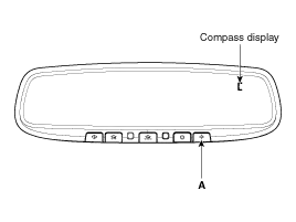
Turn on the compass by pressing the A button. |
| 3. |
Check the zone number by pressing the A button for more than 4 seconds until the current zone number appears in the display.
To re-calibrate, hold the A button for 3 seconds until C is
displayed. If the zone number is different for your country, set the
correct zone number referring to "Setting the compass zone" and do the
"calibration procedure" again. |
| 4. |
Drive your vehicle in at least 2 circles at less than 5 miles
per hour (8 km/h) until the compass heading appears. Driving in a
circle in right-handed direction and opposite direction is possible and
if possible, stops the wiper operation. |
| 5. |
If the vehicle''s compass headings become inaccurate as before, do the following procedure again.
|

Setting The Compass Zone
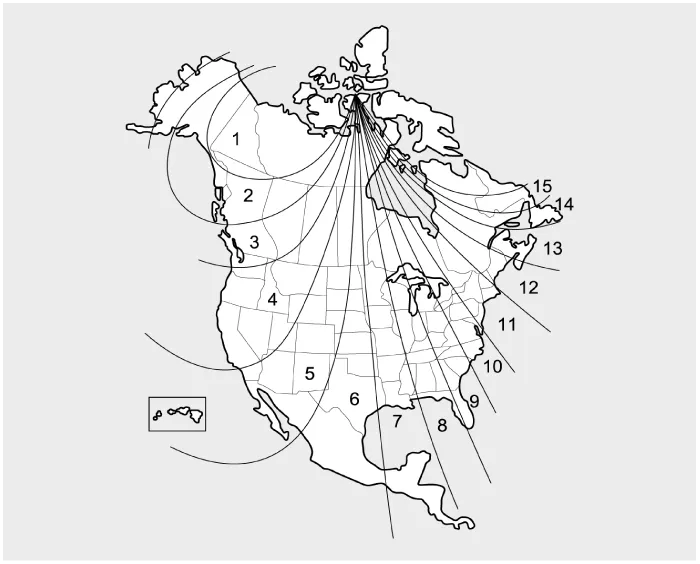
This compass must be set to compensate for the variation between true north and magnetic north. To set variation:
| 1. |
Find your current location and variance zone number on the zone map. |
| 2. |
Press the A button for more than 4 seconds. The current zone number will appear in the display. |
| 3. |
Release and press the A button until the new zone number
appears in the display. After you stop pressing the button in, the
display will show a compass direction within a few seconds.
|
Zone Map
|

Function 1. Push the A button lower of the rear view mirror to turn on the function of the compass mirror so that displays a sign of a direction on the small board in the upper-right side of the mirror.
Other information:
Kia Cadenza YG 2016-2021 Service Manual: Components and Components Location
C
Kia Cadenza YG 2016-2021 Service Manual: Auto defoging actuator Repair procedures
Inspection 1. Ignition "OFF”. 2. Disconnect the connector of auto defog control actuator. 3. Verify that the auto defog control actuator operates to the defrost ON mode when connecting 12V to the terminal 3 and grounding terminal 7. 4.
Categories
- Manuals Home
- Kia Cadenza Owners Manual
- Kia Cadenza Service Manual
- Timing Chain Repair procedures
- Restraint
- Body Control Module (BCM) Description and Operation
- New on site
- Most important about car

Copyright © 2026 www.kcadenzavg.com - 0.0438