Kia Cadenza YG: Restraint / Components and Components Location
| Components |
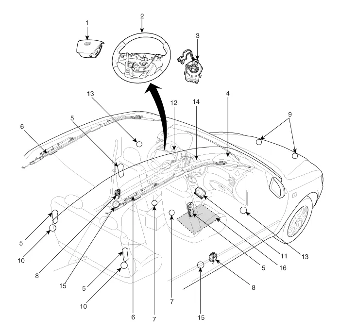
| 1. Driver Airbag (DAB) 2. Steering Wheel 3. Clock Spring 4. Passenger Airbag (PAB) 5. Side Airbag (SAB) 6. Curtain Airbag (CAB) 7. Seat Belt Buckle Switch (BS) 8. Seat Belt Pretensioner (BPT) | 9. Front Impact Sensor (FIS) 10. Rear Side Impact Sensor (RSIS) 11. Supplemental Restraint System Control Module (SRSCM) 12. Airbag Warning Lamp 13. Pressure Side Impact Sensor (P-SIS) 14. Telltale Lamp 15. Anchor Pretensioner (APT) 16. Occupant Detection System (ODS) |
| Components Location |
| Supplemental Restraint System Control Module (SRSCM) |

| Driver Airbag (DAB) / Passenger Airbag (PAB) |

| Side Airbag (SAB) |

| Curtain Airbag (CAB) |

| Seat Belt Pretensioner (BPT) |

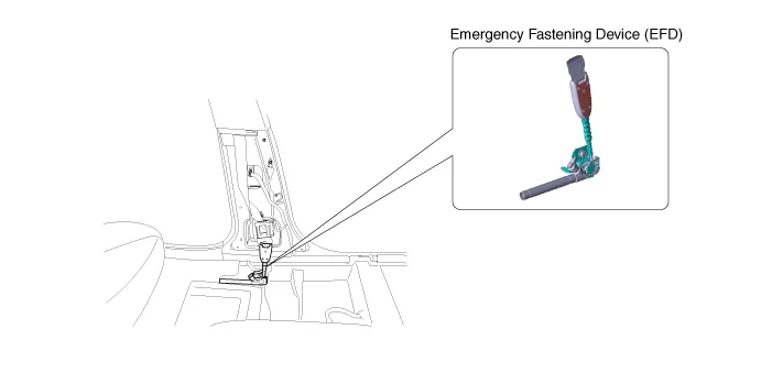
| Emergency Fastening Device (EFD) |
| Front Impact Sensor (FIS) |

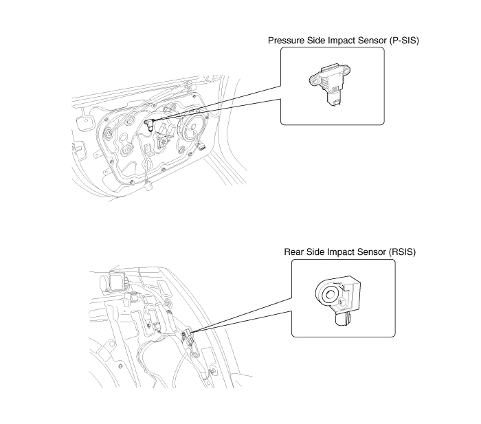
| Side Impact Sensor (SIS) / Pressure Side Impact Sensor (P-SIS) |
Tightening Torques ItemN.mkgf.mlb-ftDriver airbag (DAB)7.8 ~ 10.80.8 ~ 1.15.8 ~ 8.0Passenger airbag (PAB)7.8 ~ 11.80.8 ~ 1.25.8 ~ 8.7Curtain airbag (CAB)Bolt9.
Warning Lamp Activation Warning Lamp Behavior after Ignition On As soon as the operating voltage is applied to the SRSCM ignition input, the SRSCM activates the warning lamp for a LED lamp check.
Other information:
Kia Cadenza YG 2016-2021 Service Manual: Repair procedures
Inspection Initialization and diagnosis sequence by using diagnostic equipment Below content summarize the procedure for A/S using Diagnostic equipment Download Parameter 1. Select "AFLS" menu after selecting a vehicle. 2. Select "Parameter download" menu for define a characteristc of vehicle.
Kia Cadenza YG 2016-2021 Service Manual: Receiver-Drier Repair procedures
Replacement 1. Remove the condenser, and then remove the bottom cap (B) with L wrench (A) from the condenser. Tightening torque : 9.8~14.7N.m (1.0~1.5kgf.m, 7.2~10.8 lb-ft) 2. Remove the desiccant (A) from condenser using a long nose plier.
Categories
- Manuals Home
- Kia Cadenza Owners Manual
- Kia Cadenza Service Manual
- Engine Mechanical System
- Restraint
- Rail Pressure Sensor (RPS) Schematic Diagrams
- New on site
- Most important about car
