Kia Cadenza YG: Cruise Control System / Cruise Control Switch Repair procedures
Kia Cadenza YG 2016-2021 Service Manual / Engine Electrical System / Cruise Control System / Cruise Control Switch Repair procedures
| Removal |
| 1. |
Turn ignition switch OFF and disconnect the negative (-) battery cable. |
| 2. |
Remove the air-bag module from the steering wheel.
(Refer to Restraint - "Driver Airbag (DAB) Module and Clock Spring") |
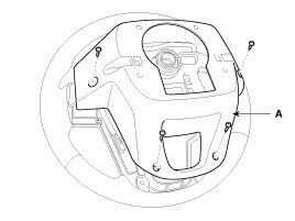
| 3. |
Remove the steering wheel cover (A) after loosening the screws.
|
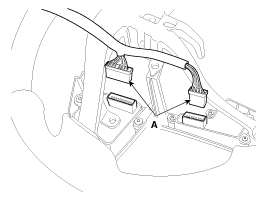
| 4. |
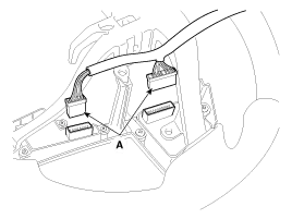
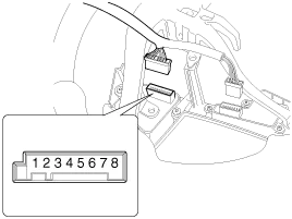
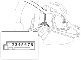
Remove the steering wheel remote control switch connector (A).
[LH]
[RH]
|
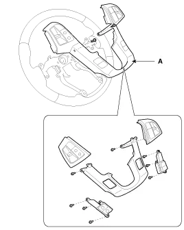
| 5. |
Remove the steering wheel remote control switch (A) after loosening the mounting screws.
|
| Installation |
| 1. |
Install in the reverse order of removal. |
| Inspection |
[Measuring Resistance]
| 1. |
Disconnect the cruise control switch connector from the control switch.
|
| 2. |
Measure resistance between terminals on the control switch when each function switch is ON (switch is depressed).
|
| 3. |
If not within specification, replace switch. |
[Measuring Voltage]
| 1. |
Connect the cruise control switch connector to the control switch.
|
| 2. |
Measure voltage between terminals on the harness side connector when each function switch is ON (switch is depressed).
|
| 3. |
If not within specification, inspect the control switch resistance.
The measuring resistance value is not within specification, replace the switch and measure the voltage again. |
| 4. |
If resistance is OK but, measuring voltage is not within
specification, inspect the wiring harness and connectors between the
switch and the ECM. |
Other information:
Kia Cadenza YG 2016-2021 Service Manual: Repair procedures
Inspection Tolerance Calibration Tolerance calibration compensates for the error margins of surround view video that occur due to the installation tolerance when the four cameras that comprise the SVM system are installed. You must carry out tolerance calibration if you do any of the following.
Kia Cadenza YG 2016-2021 Service Manual: Repair procedures
Teaching Procedures 1. Key Teaching Procedure Key teaching must be done after replacing a defective PCM(ECM) or when providing additional keys to the vehicle owner. The procedure starts with an PCM(ECM) request for vehicle specific data (PIN code: 6digits) from the tester.
Categories
- Manuals Home
- Kia Cadenza Owners Manual
- Kia Cadenza Service Manual
- General Information
- Restraint
- Engine Mechanical System
- New on site
- Most important about car

Copyright © 2026 www.kcadenzavg.com - 0.0335