
Kia Cadenza YG: Fuel Delivery System / Fuel Pressure Regulator Repair procedures
| Removal |
| 1. |
Remove the fuel pump.
(Refer to Fuel Delivery System - “Fuel Pump”) |
| 2. |
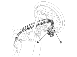
Disconnect the electric pump wiring connector (A) and the fuel sender connector (B).
|
| 3. |
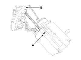
Remove the cushion pipe fixing clip (A), and then separate the head assembly (B) from reservoir cup.
|
| 4. |
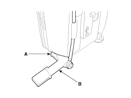
Remove the return nozzle (B) after releasing the fixing hook (A).
|
| 5. |
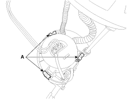
Remove the reservoir-cup after releasing the fixing hooks (A).
|
| 6. |
Remove the pre-filter (B) after releasing the fixing hooks (A).
|
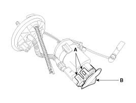

| 7. |
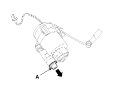
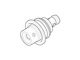
Remove the fuel pressure regulator (A) in the direction.
|
| Installation |
| 1. |
Install in the reverse order of removal. |
Removal 1. Remove the fuel pump. (Refer to Fuel Delivery System - “Fuel Pump”) 2. Disconnect the fuel sender connector (A). 3. Remove the fuel sender (A) after releasing the fix hook.
Description The fuel pump control module (FPCM) is installed on the right side of the fuel tank and controls the DC motor mounted inside the low pressure fuel pump.
Other information:
Kia Cadenza YG 2016-2021 Service Manual: Receiver-Drier Repair procedures
Replacement 1. Remove the condenser, and then remove the bottom cap (B) with L wrench (A) from the condenser. Tightening torque : 9.8~14.7N.m (1.0~1.5kgf.m, 7.2~10.8 lb-ft) 2. Remove the desiccant (A) from condenser using a long nose plier.
Kia Cadenza YG 2016-2021 Service Manual: A/C Pressure Transducer Description and Operation
Description A/C pressure transducer convert the pressure value of high pressure line into voltage value after measure it. By converted voltage value, engine ECU controls cooling fan by operating it high speed or low speed. Engine ECU stop the operation of compressor when the temperature of refrigerant line is so high or so low irregularl
Categories
- Manuals Home
- Kia Cadenza Owners Manual
- Kia Cadenza Service Manual
- General Information
- Emission Control System
- Restraint
- New on site
- Most important about car
