
Kia Cadenza YG: Brake System / Master Cylinder Repair procedures
Kia Cadenza YG 2016-2021 Service Manual / Brake System / Brake System / Master Cylinder Repair procedures
| Removal |
| 1. |
Turm ignition switch OFF and disconnect the negative (-) battery cable. |
| 2. |
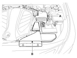
Remove the air duct (B) and air cleaner assembly (A).
|
| 3. |
Disconnect the brake fluid level switch connector (A), and remove the reservoir cap.
|

| 4. |
Remove the brake fluid from the master cylinder reservoir with a syringe.
|

| 5. |
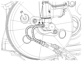
Disconnect the brake tube (C) from the master cylinder by loosening the tube flare nut.
|
| 6. |
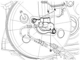
Remove the master cylinder (B) from the brake booster after loosening the mounting nuts (A).
|
| Installation |
| 1. |
Installation is the reverse of removal. |
| 2. |
After installation, bleed the brake system. (Refer to Brake system bleeding) |
Components 1. Reservoir cap2. Reservoir3. Grommet4. Master cylinder
Other information:
Kia Cadenza YG 2016-2021 Service Manual: Ambient Sensor Description and Operation
Description 1. The ambient temperature sensor is located at the front of the condenser and detects ambient air temperature. It is a negative type thermistor resistance will increase with lower temperature, and decrease with higher temperatures.
Kia Cadenza YG 2016-2021 Service Manual: Climate Control Air Filtar Repair procedures
Replacement 1. Disconnect the damper (B) from the glove box (A) and then remove the glove box lift (C). 2. Remove the filter cover (A) with pushing the knob. 3. Replace the air filter (B), install it after making sure of the direction of air filter.
Categories
- Manuals Home
- Kia Cadenza Owners Manual
- Kia Cadenza Service Manual
- Crankshaft Damper Pulley Components and Components Location
- Restraint
- Body Electrical System
- New on site
- Most important about car

Copyright © 2026 www.kcadenzavg.com - 0.0279