
Kia Cadenza YG: Button Engine Start System / Start/Stop Button Components and Components Location
| Component |
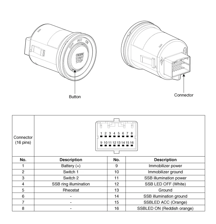
Description System Overview The System offers the following features: – Human / machine interface through a 1-stage button, for terminal switching and engine start.
Removal 1. Disconnect the negative (-) battery terminal. 2. Using a screw driver or remover, remove the center fascia lower panel (A). 3. Remove the in-car hose (A) and disconnect the connectors (B) from the heater & A/C control unit.
Other information:
Kia Cadenza YG 2016-2021 Service Manual: Auto Head lamp leveling Unit Repair procedures
Removal Height Sensor 1. Remove the height sensor connector (A). 2. Loosen the mounting bolts(Body: 2EA, chassis: 1EA) from height sensor bracket. Tightening torque : 3 ~ 5N.m (30 ~ 50kgf.m, 2.21 ~ 3.68lb-ft) 3. Remove the height sensor.
Kia Cadenza YG 2016-2021 Service Manual: Intake Actuator Repair procedures
Inspection 1. Ignition "OFF". 2. Disconnect the intake actuator connector. 3. Verify that the actuator operates to the recirculation position when connecting 12V to the terminal 3 and grounding terminal 7. 4. Verify that the intake actuator operates to the fresh position when connecting in the reverse.
Categories
- Manuals Home
- Kia Cadenza Owners Manual
- Kia Cadenza Service Manual
- Crankshaft Damper Pulley Components and Components Location
- Engine Control / Fuel System
- Suspension System
- New on site
- Most important about car
