Kia Cadenza YG: Starting System / Starter Relay Repair procedures
Kia Cadenza YG 2016-2021 Service Manual / Engine Electrical System / Starting System / Starter Relay Repair procedures
| Inspection |
| 1. |
Disconnect the battery negative terminal. |
| 2. |
Remove the fuse box cover. |
| 3. |
Remove the starter relay (A).
|

| 4. |
Check for continuity between the terminals (30 and 87) using an ohmmeter.
| ||||||||||
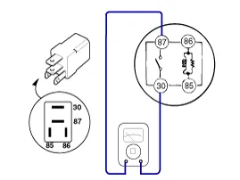
| 5. |
Apply 12V to the terminal 85 and ground to the terminal 86 and then check for continuity between the terminals (30 and 87).
| ||||||||||

| 6. |
Install the starter relay. |
| 7. |
Install the fuse box cover. |
Removal 1. Turn the ignition switch OFF and disconnect the battery negative (-) cable. 2. Remove the under (A) and (B). 3. Remove the starter cover (A).
Other information:
Kia Cadenza YG 2016-2021 Service Manual: Blind Spot Detection Unit Repair procedures
Removal 1. Disconnect the negative (-) battery terminal. 2. Remove the rear bumper. (Refer to Body - "Rear Bumper") 3. Remove the BSD unit (A) after loosening the mounting screws. Take care not to separate the bracket from rear bumper when removing the BSD sensor.
Kia Cadenza YG 2016-2021 Service Manual: Ambient Sensor Description and Operation
Description 1. The ambient temperature sensor is located at the front of the condenser and detects ambient air temperature. It is a negative type thermistor resistance will increase with lower temperature, and decrease with higher temperatures.
Categories
- Manuals Home
- Kia Cadenza Owners Manual
- Kia Cadenza Service Manual
- Engine Electrical System
- General Information
- Timing Chain Repair procedures
- New on site
- Most important about car

Copyright © 2026 www.kcadenzavg.com - 0.0311