Kia Cadenza YG: Indicators And Gauges / Components and Components Location
| Component Location |
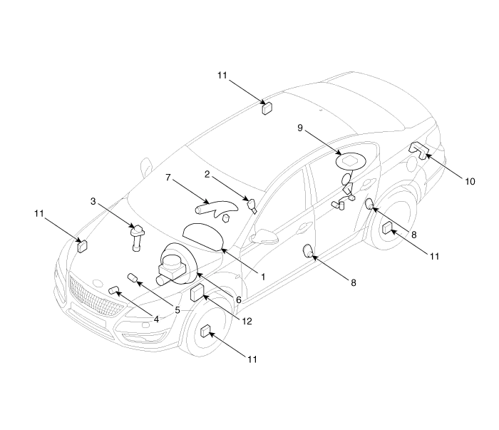
| 1. Instrument cluster assembly 2. Seat belt switch 3. Vehicle speed sensor 4. Engine coolant temperature sender 5. Oil pressure switch 6. Brake fluid level warning switch | 7. Parking brake switch 8. Door switch 9. Fuel gauge sender 10. Trunk lid open switch 11. Wheel speed sensor 12. ABS ECU |
Components Connector Pin Information No.DescriptionNo.Description1Air bag (+)21Aig bag (-)2Trip switch (+)22Speaker output (+)3Cruise switch (+)23Speaker output (-)4Rheostat down switch (-)24Trip switch (-)5Rheostat up switch (-)25VS 4P output (-)6Oil pressure (-)26AT R output (+)7Washer indicator (-)27AT P output (+)8Battery charge (-)28Detent output (+)9H/SWHL indicator (+)29Immobilizer (-)10Brake oil switch (-)30MM CAN high11Active ECO switch (-)31MM CAN low12Driving mode switch (-)32C CAN low13AT D output (+)33C CAN high14Fuel (+)34AT N output (+)15AT S output (+)(AT)35Illumniation (-)16Fuel (-)36P ground17-37S ground18Glass status signal (-)38-19-39IGN 1 (+)20Illumination (+)40Battery (+)
Other information:
Kia Cadenza YG 2016-2021 Service Manual: Specifications
S
Kia Cadenza YG 2016-2021 Service Manual: A/C Pressure Transducer Description and Operation
Description A/C pressure transducer convert the pressure value of high pressure line into voltage value after measure it. By converted voltage value, engine ECU controls cooling fan by operating it high speed or low speed. Engine ECU stop the operation of compressor when the temperature of refrigerant line is so high or so low irregularl
Categories
- Manuals Home
- Kia Cadenza Owners Manual
- Kia Cadenza Service Manual
- Battery Troubleshooting
- Steering System
- Engine Mechanical System
- New on site
- Most important about car
