Kia Cadenza YG: Indicators And Gauges / Instrument Cluster Components and Components Location
Kia Cadenza YG 2016-2021 Service Manual / Body Electrical System / Indicators And Gauges / Instrument Cluster Components and Components Location
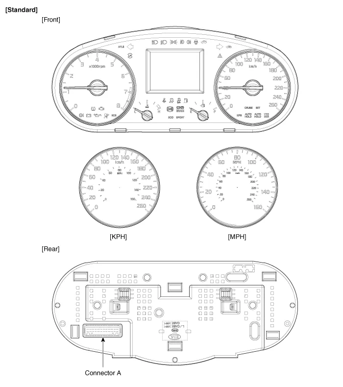
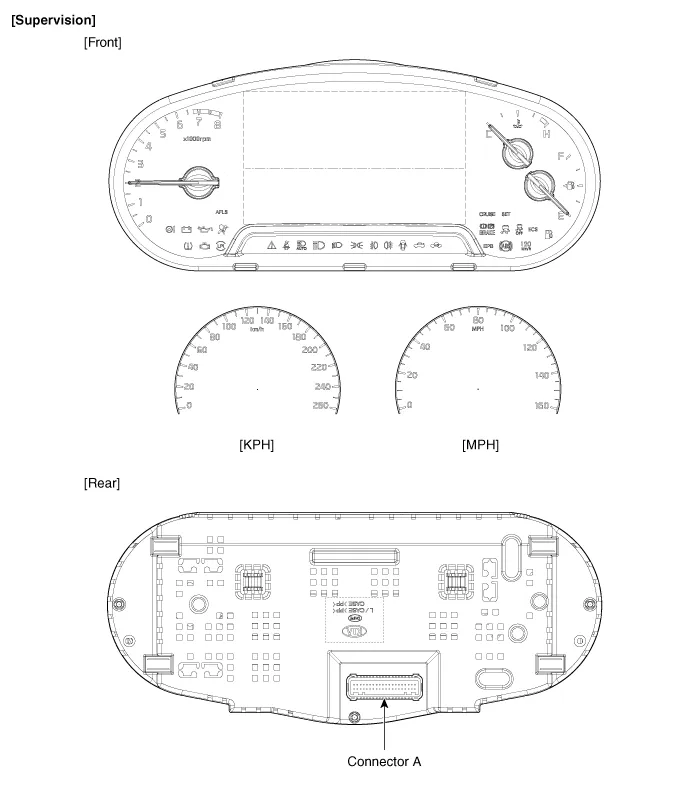
| Components |
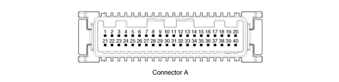
Connector Pin Information
| No. | Description | No. | Description |
| 1 | Air bag (+) | 21 | Aig bag (-) |
| 2 | Trip switch (+) | 22 | Speaker output (+) |
| 3 | Cruise switch (+) | 23 | Speaker output (-) |
| 4 | Rheostat down switch (-) | 24 | Trip switch (-) |
| 5 | Rheostat up switch (-) | 25 | VS 4P output (-) |
| 6 | Oil pressure (-) | 26 | AT R output (+) |
| 7 | Washer indicator (-) | 27 | AT P output (+) |
| 8 | Battery charge (-) | 28 | Detent output (+) |
| 9 | H/SWHL indicator (+) | 29 | Immobilizer (-) |
| 10 | Brake oil switch (-) | 30 | MM CAN high |
| 11 | Active ECO switch (-) | 31 | MM CAN low |
| 12 | Driving mode switch (-) | 32 | C CAN low |
| 13 | AT D output (+) | 33 | C CAN high |
| 14 | Fuel (+) | 34 | AT N output (+) |
| 15 | AT S output (+)(AT) | 35 | Illumniation (-) |
| 16 | Fuel (-) | 36 | P ground |
| 17 | - | 37 | S ground |
| 18 | Glass status signal (-) | 38 | - |
| 19 | - | 39 | IGN 1 (+) |
| 20 | Illumination (+) | 40 | Battery (+) |
Component Location 1. Instrument cluster assembly2. Seat belt switch3. Vehicle speed sensor4. Engine coolant temperature sender5. Oil pressure switch6.
Circuit Diagram
Other information:
Kia Cadenza YG 2016-2021 Service Manual: Antenna Coil Repair procedures
Removal 1. Disconnect the negative (-) battery terminal. 2. Remove the crash pad lower panel. (Refer to Body - "Crash Pad") 3. Disconnect the 6P connector (B) of the coil antenna and then remove the coil antenna (A) after loosening the screw.
Kia Cadenza YG 2016-2021 Service Manual: Compressor Components and Components Location
C
Categories
- Manuals Home
- Kia Cadenza Owners Manual
- Kia Cadenza Service Manual
- Battery Troubleshooting
- Transaxle Control Module (TCM) Repair procedures
- Engine Mechanical System
- New on site
- Most important about car

Copyright © 2026 www.kcadenzavg.com - 0.0243