Kia Cadenza YG: Adaptive Front Lighting System / Description and Operation
Kia Cadenza YG 2016-2021 Service Manual / Body Electrical System / Adaptive Front Lighting System / Description and Operation
| Description |
Adaptive Front-lighting System (AFLS)
AFLS(Adaptive Front-lighting System)is a headlamp
orientation control system that takes into account both steering angle
and vehicle speed to orient the headlamps to an angle that provides
better nighttime visibility.
Variable conditions make lighting pattern of running vehicle kaleidoscope.
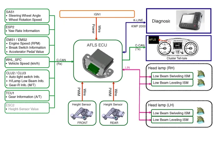
Component of AFLS
| 1. |
Input part : It is provided that information of speed sensor, height sensor and so on related to condition of vehicle. |
| 2. |
Control part (AFLS Unit) : It controls Output part by analyzing/judging Input signal. |
| 3. |
Output part : It drive Low beam of H/Lamp to upper/lower and
left/right side optimum lighting pattern according to output control
signal of AFLS Unit. |
Main function of AFLS
| Content | Description | |||||||||
| 1 | Dynamic Bending (Swivelling) |
| ||||||||
| 2 | Automatic Leveling (Leveling) |
| ||||||||
| 3 | Fail-safe |
|
Advantage of AFLS
| Content | Description | |||||||
| 1 | Enhanced stability |
| ||||||
| 2 | Enhanced convenience |
|
Block Diagram
| Operation |
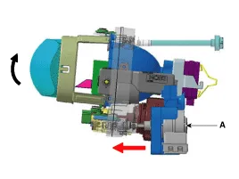
Component
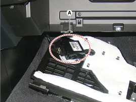
AFLS Unit (A)
| 1. |
General
System initialization, In case of input Engine signal (AFLS ECU, Levelling /Swivelling motor)
Adaptation of AFLS OFF switch
AFLS operate normally ,only under turning auto light switch on.
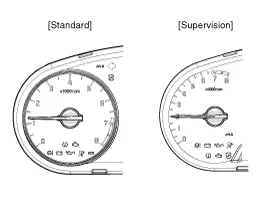
Providing Tel-tale function of AFLS (display ‘AFLS’ on dashboard).
In case of system failure, display light on ‘AFLS’ on dashboard
|
| 2. |
Main function
Swivelling function
Levelling function
Processing signal of Height sensor
Control the clynamic bending light |
Swivelling Motor (A)
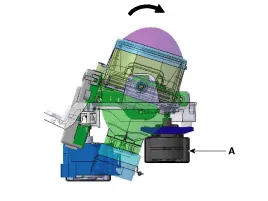
| 1. |
General
communicate AFLS Unit through LIN protocol
Robust control to Disturbance
Doesn''t work out of rated voltage range. |
| 2. |
Main function & Rating
Drive Low beam to left / right side
Fail-safe function : In case of detecting malfunction or system failure , drive to secure position |
Levelling Motor (A)
| 1. |
Main spec
communicate AFLS Unit through LIN protocol
Robust control to Disturbance
Doesn''t work out of rated voltage range. |
| 2. |
Main function & Rating
Drive Low beam to upper / lower
Fail-safe function : In case of detecting malfunction or system failure , drive to secure position |
Height Sensor
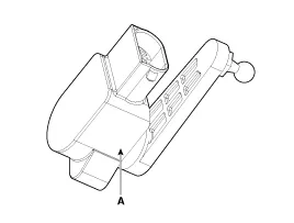
| 1. |
General
Height Sensor connecting body & suspension measures inclination information from load condition.
Vehicle having the Steel-suspension system transmits inclination signal to AFLS ECU by using Hard-wire. |
| 2. |
Rating
Rated Voltage : 5V ± 5% |
Circuit Diagram
Inspection Initialization and diagnosis sequence by using diagnostic equipment Below content summarize the procedure for A/S using Diagnostic equipment Download Parameter 1.
Other information:
Kia Cadenza YG 2016-2021 Service Manual: Lane Departure Warning System (LDWS) Unit Repair procedures
Removal 1. Disconnect the negative (-) battery terminal. 2. Remove the LDWS unit cover (A). 3. Remove the LDWS unit connector (A). 4. Remove the LDWS unit after widening the mounting clips. Installation 1. Install the LDWS unit. 2.
Kia Cadenza YG 2016-2021 Service Manual: Troubleshooting
Troubleshooting Problem Symptoms Table Before replacing or repairing air conditioning components, first determine if the malfunction is due to the refrigerant charge, air flow or compressor. Use the table below to help you find the cause of the problem.
Categories
- Manuals Home
- Kia Cadenza Owners Manual
- Kia Cadenza Service Manual
- Automatic Transaxle System
- Emission Control System
- Body Electrical System
- New on site
- Most important about car

Copyright © 2026 www.kcadenzavg.com - 0.0222