Kia Cadenza YG: Air Conditioning System / Photo Sensor Repair procedures
Kia Cadenza YG 2016-2021 Service Manual / Heating,Ventilation, Air Conditioning / Air Conditioning System / Photo Sensor Repair procedures
| Inspection |
| 1. |
Ignition "ON" |
| 2. |
Using the scan tool. |
| 3. |
Emit intensive light toward photo sensor using a lamp, and check the output voltage change. |
| 4. |
The voltage will rise with higher intensive light and reduce with lower intensive light.
|

| Replacement |
| 1. |
Disconnect the negative (-) battery terminal. |
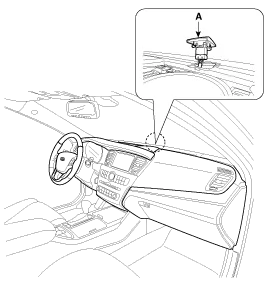
| 2. |
With the (-) driver, remove the photo sensor (A) from the center of defrost nozzle.
|
| 3. |
Install in the reverse order of removal. |
Description 1. The photo sensor is located at the center of defrost nozzle. 2. The photo sensor contains a photovoltaic (sensitive to sunlight) diode.
Description 1. The ambient temperature sensor is located at the front of the condenser and detects ambient air temperature. It is a negative type thermistor resistance will increase with lower temperature, and decrease with higher temperatures.
Other information:
Kia Cadenza YG 2016-2021 Service Manual: Description and Operation
Description Surround View Monitoring System (SVM) is the system that allows video monitoring of 360 degrees around the vehicle. The system includes 4 ultra optical camera mounted around the vehicle (front, both sides, rear). The video from these cameras are applied with distortion compensation, time point conversion, and video merging
Kia Cadenza YG 2016-2021 Service Manual: Components and Components Location
C
Categories
- Manuals Home
- Kia Cadenza Owners Manual
- Kia Cadenza Service Manual
- Engine Mechanical System
- Timing Chain Repair procedures
- Engine Electrical System
- New on site
- Most important about car

Copyright © 2026 www.kcadenzavg.com - 0.0237