Kia Cadenza YG: Blower / Intake Actuator Repair procedures
| Inspection |
| 1. |
Ignition "OFF". |
| 2. |
Disconnect the intake actuator connector. |
| 3. |
Verify that the actuator operates to the recirculation position when connecting 12V to the terminal 3 and grounding terminal 7. |
| 4. |
Verify that the intake actuator operates to the fresh position when connecting in the reverse.
|

| 5. |
Check the voltage between terminals 5 and 6.
Specification
|
| 6. |
If the intake actuator is not operated well, substitute with a known-good intake actuator and check for proper operation. |
| 7. |
If the problem is corrected, replace the intake actuator. |
| Replacement |
| 1. |
Disconnect the negative (-) battery terminal. |
| 2. |
Remove the crash pad.
(Refer to BD group – "Crash pad") |
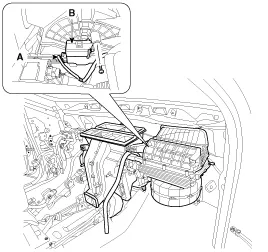
| 3. |
Disconnect the Intake actuator connector (A). |
| 4. |
Loosen the mounting screw and then remove the intake actuator (B). |
| 5. |
Installation is the reverse order of removal.
|
Description 1. The intake actuator is located at the blower unit. 2. It regulates the intake door by signal from control unit. 3. Pressing the intake selection switch will shift between recirculation and fresh air modes.
Other information:
Kia Cadenza YG 2016-2021 Service Manual: Repair procedures
Removal 1. Remove the trunk trim in the trunk after removing the screws and clips. (Refer to Body - "Trunk") 2. Remove the camera holder (A) as shown arrow direction, and then remove the back view camera (B). Installation 1. Install the back view camera and camera holder.
Kia Cadenza YG 2016-2021 Service Manual: Heater Unit Repair procedures
Replacement 1. Disconnect the negative (-) battery terminal. 2. Recover the refrigerant with a recovery/ recycling/ charging station. 3. When the engine is cool, drain the engine coolant from the radiator. 4. Remove the expansion valve cover (A).
Categories
- Manuals Home
- Kia Cadenza Owners Manual
- Kia Cadenza Service Manual
- Schematic Diagrams
- Components and Components Location
- Brake System
- New on site
- Most important about car
