Kia Cadenza YG: Engine Control System / Components and Components Location
| Components Location |
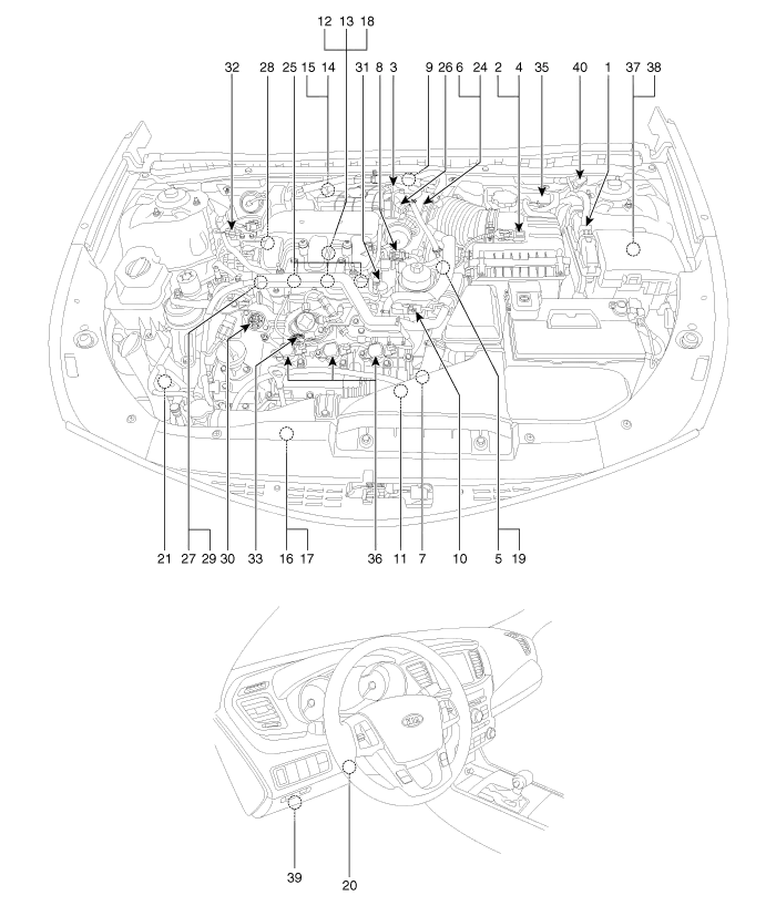
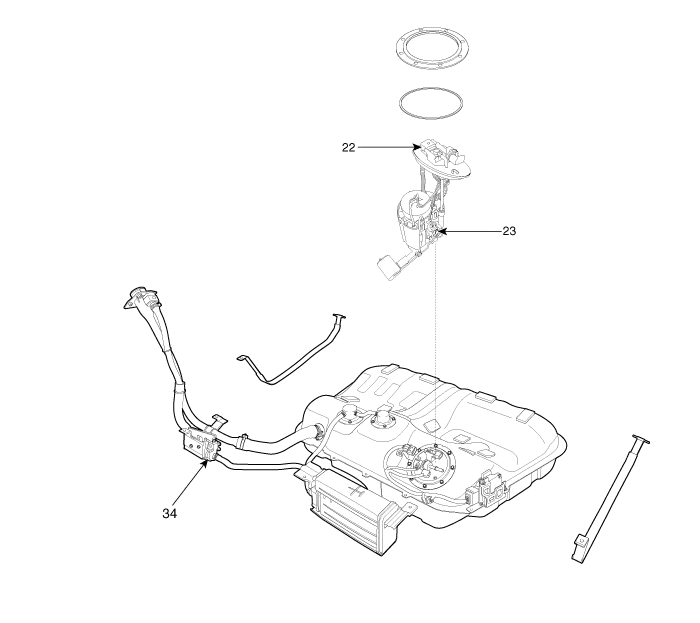
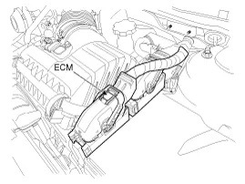
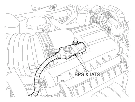
| 1. ECM (Engine Control Module) 2. Barometric Pressure Sensor (BPS) 3. Manifold Absolute Pressure Sensor (MAPS) 4. Intake Air Temperature Sensor (IATS) 5. Engine Coolant Temperature Sensor (ECTS) 6. Throttle Position Sensor (TPS) [integrated into ETC Module] 7. Crankshaft Position Sensor (CKPS) 8. Camshaft Position Sensor (CMPS) [Bank 1 / Intake] 9. Camshaft Position Sensor (CMPS) [Bank 1 / Exhaust] 10. Camshaft Position Sensor (CMPS) [Bank 2 / Intake] 11. Camshaft Position Sensor (CMPS) [Bank 2 / Exhaust] 12. Knock Sensor (KS) [Bank 1] 13. Knock Sensor (KS) [Bank 2] 14. Heated Oxygen Sensor (HO2S) [Bank 1 / Sensor 1] 15. Heated Oxygen Sensor (HO2S) [Bank 1 / Sensor 2] 16. Heated Oxygen Sensor (HO2S) [Bank 2 / Sensor 1] 17. Heated Oxygen Sensor (HO2S) [Bank 2 / Sensor 2] 18. Rail Pressure Sensor (RPS) 19. CVVT Oil Temperature Sensor (OTS) 20. Accelerator Position Sensor (APS) | 21. A/C Pressure Transducer (APT) 22. Fuel Tank Pressure Sensor (FTPS) 23. Fuel Level Sender (FLS) 24. ETC Motor [integrated into ETC Module] 25. Injector 26. Purge Control Solenoid Valve (PCSV) 27. CVVT Oil Control Valve (OCV) [Bank 1 / Intake] 28. CVVT Oil Control Valve (OCV) [Bank 1 / Exhaust] 29. CVVT Oil Control Valve (OCV) [Bank 2 / Intake] 30. CVVT Oil Control Valve (OCV) [Bank 2 / Exhaust] 31. Variable Intake Solenoid (VIS) Valve #1 32. Variable Intake Solenoid (VIS) Valve #2 33. Fuel Pressure Control Valve (FPCV) 34. Canister Close Valve (CCV) 35. Injector Drive Box (IDB) 36. Ignition Coil 37. Main Relay 38. Fuel Pump Relay 39. Data Link Connector (DLC) [16 Pin] 40. Multi-Purpose Check Connector [20 Pin] |
| 1. ECM (Engine Control Module) | 2. Barometric Pressure Sensor (BPS) 4. Intake Air Temperature Sensor (IATS) |
|
|
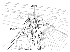
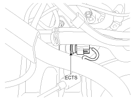
| 3. Manifold Absolute Pressure Sensor (MAPS) 6. Throttle Position Sensor (TPS) [integrated into ETC Module] 26. Purge Control Solenoid Valve (PCSV) | 5. Engine Coolant Temperature Sensor (ECTS) |
|
|
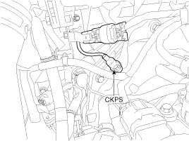
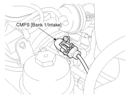
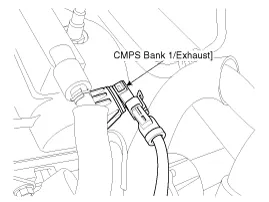
| 7. Crankshaft Position Sensor (CKPS) | 8. Camshaft Position Sensor (CMPS) [Bank 1 / Intake] |
|
|
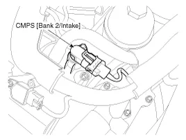
| 9. Camshaft Position Sensor (CMPS) [Bank 1 / Exhaust] | 10. Camshaft Position Sensor (CMPS) [Bank 2 / Intake] |
|
|
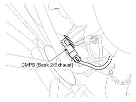
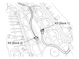
| 11. Camshaft Position Sensor (CMPS) [Bank 2 / Exhaust] | 12. Knock Sensor (KS) [Bank 1] 13. Knock Sensor (KS) [Bank 2] |
|
|
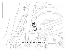
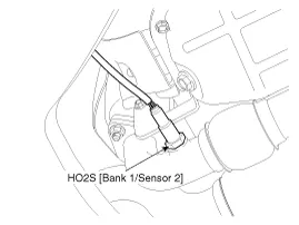
| 14. Heated Oxygen Sensor (HO2S) [Bank 1 / Sensor 1] | 15. Heated Oxygen Sensor (HO2S) [Bank 1 / Sensor 2] |
|
|
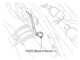
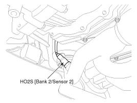
| 16. Heated Oxygen Sensor (HO2S) [Bank 2 / Sensor 1] | 17. Heated Oxygen Sensor (HO2S) [Bank 2 / Sensor 2] |
|
|
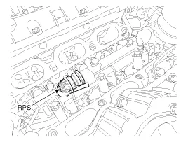
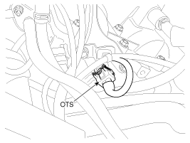
| 18. Rail Pressure Sensor (RPS) | 19. CVVT Oil Temperature Sensor (OTS) |
|
|
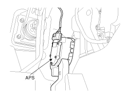
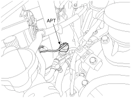
| 20. Accelerator Position Sensor (APS) | 21. A/C Pressure Transducer (APT) |
|
|
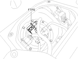
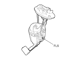
| 22. Fuel Tank Pressure Sensor (FTPS) | 23. Fuel Level Sender (FLS) |
|
|
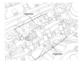
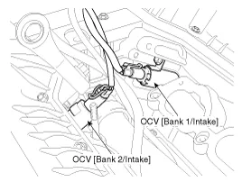
| 25. Injector | 27. CVVT Oil Control Valve (OCV) [Bank 1 / Intake] 29. CVVT Oil Control Valve (OCV) [Bank 2 / Intake] |
|
|
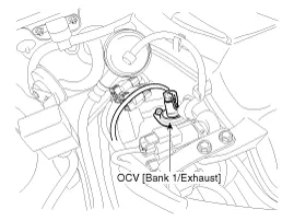
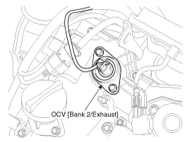
| 28. CVVT Oil Control Valve (OCV) [Bank 1 / Exhaust] | 30. CVVT Oil Control Valve (OCV) [Bank 2 / Exhaust] |
|
|
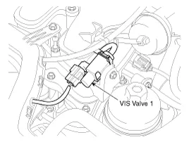
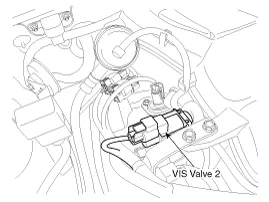
| 31. Variable Intake Solenoid (VIS) Valve #1 | 32. Variable Intake Solenoid (VIS) Valve #2 |
|
|
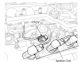
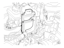
| 33. Fuel Pressure Control Valve (FPCV) 36. Ignition Coil | 35. Injector Drive Box (IDB) |
|
|
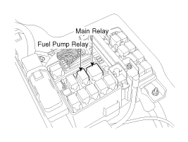
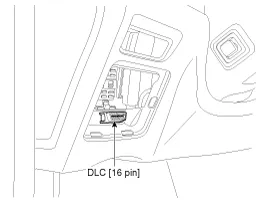
| 37. Main Relay 38. Fuel Pump Relay | 39. Data Link Connector (DLC) [16 Pin] |
|
|
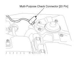
| 40. Multi-Purpose Check Connector [20 Pin] | |
|
OBD-II review 1. Overview The California Air Resources Board (CARB) began regulation of On Board Diagnostics (OBD) for vehicles sold in California beginning with the 1988 model year.
ECM Terminal And Input/Output signal ECM Terminal Function Connector [E600-A] Pin No.DescriptionConnected to1- 2- 3- 4Immobilizer Lamp control outputImmobilizer Lamp [Without Button Engine Start System]5Power groundChassis Ground6Power groundChassis Ground7- 8- 92nd CAN [High]Multi-Purpose Check Connector10CAN [High]Other control module, Data Link Connector (DLC), Multi-Purpose Check Connector11Fuel Tank Pressure Sensor (FTPS) signal inputFuel Tank Pressure Sensor (FTPS)12Electrical Load signal inputHead Lamp Relay13- 14Sensor power (+5V)Accelerator Position Sensor (APS) 115Sensor power (+5V)A/C Pressure Transducer (APT)Rail Pressure Sensor (RPS)16Fuel Level Sender (FLS) signal inputFuel Level Sender (FLS)17-18- 19- 20A/C Compressor relay signal outputA/C Control Module21Brake Switch 2 signal inputBrake Switch22- 23- 24Alternator PWM signal input [FR]Alternator25-26- 27Battery power (B+)Ignition Switch28Rail Pressure Sensor (RPS) signal inputRail Pressure Sensor (RPS)29- 30Power groundChassis Ground31- 32- 33- 342nd CAN [Low]Multi-Purpose Check Connector35CAN [Low]Other control module, Data Link Connector (DLC), Multi-Purpose Check Connector36- 37Sensor groundRail Pressure Sensor (RPS)38Accelerator Position Sensor (APS) 1 signal inputAccelerator Position Sensor (APS) 139- 40- 41-42A/C Switch "ON" signal inputA/C Control Module43Brake Switch 1 signal inputBrake Switch44- 45- 46- 47- 48-49- 50- 51- 52Battery power (B+)Battery53- 54- 55Power groundChassis Ground56- 57A/C Compressor Clutch Relay control outputA/C Control Module [With Immobilzer]58- 59Sensor groundAccelerator Position Sensor (APS) 260Sensor groundAccelerator Position Sensor (APS) 161Sensor groundFuel Tank Pressure Sensor (FTPS)62GroundCruise Control Switch63Sensor groundA/C Pressure Transducer (APT)64- 65Sensor Power (+5V)Fuel Tank Pressure Sensor (FTPS)66Cruise Control Switch signal inputCruise Control Switch67A/C Pressure Transducer (APT) signal inputA/C Pressure Transducer (APT)68Accelerator Position Sensor (APS) 2 signal inputAccelerator Position Sensor (APS) 269-70Engine speed signal outputPower Distribution Module (PDM)71Cooling Fan Relay [High] control outputCooling Fan Relay [High]72Alternator PWM signal output (COM)Alternator73- 74Immobilizer communication lineSmart Key Control Module [With Button Engine Start System]Immobilizer Control Unit [Without Button Engine Start System]75Battery power (B+)Main Relay76- 77Battery power (B+)Battery78-79- 80Power groundChassis ground81- 82- 83- 84- 85- 86- 87LIN (Local Interconnect Network) Serial Bus LineBattery Sensor88- 89- 90Sensor power (+5V)Accelerator Position Sensor (APS) 291Cooling Fan Relay [Low] control outputCooling Fan Relay [Low]92- 93Starter Relay control outputStarter Relay94Main Relay control outputMain Relay95Fuel pump Relay control outputFuel pump Relay 96Canister Close Valve (CCV) control outputCanister Close Valve (CCV)97- 98- 99Battery power (B+)Main Relay100Battery power (B+)Main Relay Connector [C600-B] Pin No.
Other information:
Kia Cadenza YG 2016-2021 Service Manual: Description and Operation
System Overview RPAS (Rear Parking Assist System) is an electronic driving aid that warns the driver to be cautious while parking or in low speed environments. The sensor uses ultrasonic waves to detect objects within proximity of the vehicle.
Kia Cadenza YG 2016-2021 Service Manual: Troubleshooting
Troubleshooting Examples of False-Alarm Occurrence from system characteristics (It’s not a problem) – Characteristics of EM Wave : EM Waves are reflected against all material and especially metal very well. Reflections of EM Waves are varies with the shape of object.
Categories
- Manuals Home
- Kia Cadenza Owners Manual
- Kia Cadenza Service Manual
- Battery Troubleshooting
- Emission Control System
- Body Electrical System
- New on site
- Most important about car
