Kia Cadenza YG: Indicators And Gauges / Components and Components Location
Kia Cadenza YG 2016-2021 Service Manual / Body Electrical System / Indicators And Gauges / Components and Components Location
| Component Location |
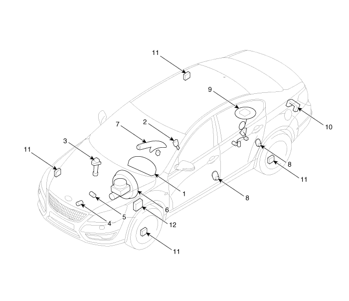
| 1. Instrument cluster assembly 2. Seat belt switch 3. Vehicle speed sensor 4. Engine coolant temperature sender 5. Oil pressure switch 6. Brake fluid level warning switch | 7. Parking brake switch 8. Door switch 9. Fuel gauge sender 10. Trunk lid open switch 11. Wheel speed sensor 12. ABS ECU |
Components Connector Pin Information No.DescriptionNo.Description1Air bag (+)21Aig bag (-)2Trip switch (+)22Speaker output (+)3Cruise switch (+)23Speaker output (-)4Rheostat down switch (-)24Trip switch (-)5Rheostat up switch (-)25VS 4P output (-)6Oil pressure (-)26AT R output (+)7Washer indicator (-)27AT P output (+)8Battery charge (-)28Detent output (+)9H/SWHL indicator (+)29Immobilizer (-)10Brake oil switch (-)30MM CAN high11Active ECO switch (-)31MM CAN low12Driving mode switch (-)32C CAN low13AT D output (+)33C CAN high14Fuel (+)34AT N output (+)15AT S output (+)(AT)35Illumniation (-)16Fuel (-)36P ground17-37S ground18Glass status signal (-)38-19-39IGN 1 (+)20Illumination (+)40Battery (+)
Categories
- Manuals Home
- Kia Cadenza Owners Manual
- Kia Cadenza Service Manual
- Engine Electrical System
- Body Electrical System
- Engine Mechanical System
- New on site
- Most important about car

Copyright © 2026 www.kcadenzavg.com - 0.0297