Kia Cadenza YG: Brake System / Front Disc Brake Repair procedures
| Removal |
| 1. |
Remove the front wheel & tire.
|
| 2. |
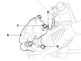
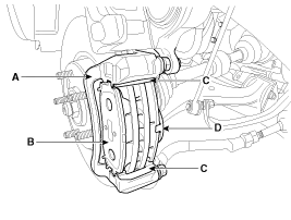
Loosen the hose eyebolt (C) and caliper mounting bolts (B), then remove the front caliper assembly (A).
|
| 3. |
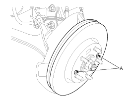
Remove the front brake disc by loosening the screws (A).
|
| Replacement |
| 1. |
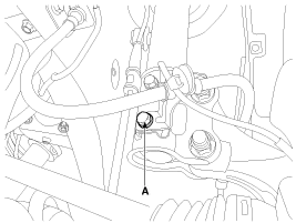
Remove the brake hose mounting bracket bolt (A).
|
| 2. |
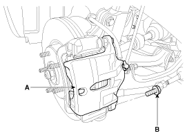
Loosen the guide rod bolt (B) and pivot the caliper (A) up out of the way.
|
| 3. |
Replace pad shim (D), pad retainers (C) and brake pads (B) in the caliper carrier (A).
|
| Inspection |
| 1. |
Check the brake pads for wear and fade. |
| 2. |
Check the brake disc for damage and cracks. |
| 3. |
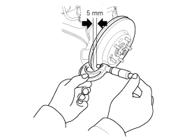
Remove all rust and contamination from the surface, and
measure the disc thickness at 8 points, at least, of same distance (5mm)
from the brake disc outer circle.
|
| 4. |
If wear exceeds the limit, replace the discs and pad assembly left and right of the vehicle. |
| 1. |
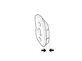
Check the pad wear. Measure the pad thickness and replace it, if it is less than the specified value.
|
| 2. |
Check that grease is applied, to sliding contact points and the pad and backing metal for damage.
|
| 1. |
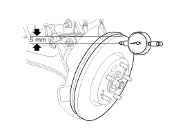
Place a dial gauge about 5mm (0.2 in.) from the outer circumference of the brake disc, and measure the runout of the disc.
|
| 2. |
If the runout of the brake disc exceeds the limit specification, replace the disc, and then measure the runout again. |
| 3. |
If the runout does not exceed the limit specification,
install the brake disc after turning it 180° and then check the runout
of the brake disc again. |
| 4. |
If the runout cannot be corrected by changing the position of the brake disc, replace the brake disc. |
| Installation |
| 1. |
Installation is the reverse of removal. |
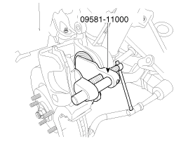
| 2. |
Use a SST (09581-11000) when installing the brake caliper assembly.
|
| 3. |
After installation, bleed the brake system. (Refer to Brake system bleeding) |
Components 1. Guide rod bolt2. Bleed screw3. Caliper carrier4. Caliper body5. Inner pad shim6. Brake pad7. Pad retainer
Components (Without EPB) 1. Guide rod bolt2. Bleed screw3. Caliper carrier4. Caliper body5. Inner pad shim6. Brake pad7. Pad retainer Components (With EPB) 1.
Other information:
Kia Cadenza YG 2016-2021 Service Manual: Description and Operation
Description The immobilizer system will disable the vehicle unless the proper ignition key is used, in addition to the currently available anti-theft systems such as car alarms, the immobilizer system aims to drastically reduce the rate of auto theft.
Kia Cadenza YG 2016-2021 Service Manual: Ambient Sensor Description and Operation
Description 1. The ambient temperature sensor is located at the front of the condenser and detects ambient air temperature. It is a negative type thermistor resistance will increase with lower temperature, and decrease with higher temperatures.
Categories
- Manuals Home
- Kia Cadenza Owners Manual
- Kia Cadenza Service Manual
- Timing Chain Repair procedures
- Transaxle Control Module (TCM) Repair procedures
- Engine Mechanical System
- New on site
- Most important about car
