Kia Cadenza YG: Fuel Delivery System / Fuel Pump Repair procedures
| Inspection |
| 1. |
Turn the ignition switch OFF, and then remove battery (-) cable. |
| 2. |
Remove the fuel pump assembly. |
| 3. |
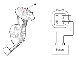
Check that motor operates properly when applying battery voltage to terminals 2 and 4 of fuel pump connector (A).
|
| 1. |
Turn the ignition switch OFF, and then remove battery (-) cable. |
| 2. |
Remove the fuel pump assembly. |
| 3. |
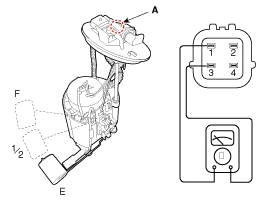
Using an ohmmeter, measure the resistance between terminals 1 and 3 of sender connector (A) at each float level.
|
| 4. |
Also check that the resistance changes smoothly when the float is moved from "E" to "F".
[ Analog cluster type]
[Digital cluster type]
|
| Removal |
| 1. |
Release the residual pressure in fuel line.
(Refer to the Fuel Delivery System - Repair Procedures - "Release Residual Pressure in Fuel Line"). |
| 2. |
Remove the floor mat after open the trunk. |
| 3. |
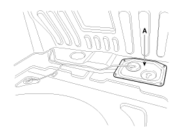
Remove the fuel pump service cover (A) in the trunk.
|
| 4. |
Disconnect the fuel pump control module & fuel pump extension connector (A). |
| 5. |
Disconnect the fuel feed tube quick-connector (B). |
| 6. |
Disconnect the fuel tank pressure sensor connector (C). |
| 7. |
Disconnect the fuel tank tank pressure sensor connector (D). |
| 8. |
Remove the fuel pump plate cover (E) after removing the bolts. |
| 9. |
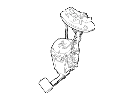
Remove the fuel pump from the fuel tank.
|

| Installation |
| 1. |
Install in the reverse order of removal.
|

Removal 1. Release the residual pressure in fuel line. (Refer to the Fuel Delivery System - Repair Procedures - "Release Residual Pressure in Fuel Line").
Removal 1. Remove the fuel pump. (Refer to Fuel Delivery System - “Fuel Pump”) 2. Disconnect the electric pump wiring connector (A) and the fuel sender connector (B).
Other information:
Kia Cadenza YG 2016-2021 Service Manual: Height Sensor Repair procedures
Removal Height Sensor 1. Disconnect the negative (-) battery terminal. 2. Remove the height sensor linkage (A) installed on the front axle and rear axle. [Front] [Rear] Installation Height Sensor 1. Install the height sensor assembly after connecting the connector.
Kia Cadenza YG 2016-2021 Service Manual: Blower Resistor Repair procedures
Inspection 1. Measure terminal - to - terminal resistance of blower resistor. 2. If measure resistance isnot within specification, the blower resistor must be replaced. Replacement 1. Disconnect the negative (-) battery terminal. 2. Remove the crash pad lower cover (A) and then disconnect the connector (B).
Categories
- Manuals Home
- Kia Cadenza Owners Manual
- Kia Cadenza Service Manual
- Engine Mechanical System
- Timing Chain Repair procedures
- Engine Control / Fuel System
- New on site
- Most important about car
