Kia Cadenza YG: Fuel Delivery System / Fuel Tank Repair procedures
| Removal |
| 1. |
Release the residual pressure in fuel line.
(Refer to the Fuel Delivery System - Repair Procedures - "Release Residual Pressure in Fuel Line"). |
| 2. |
Remove the floor mat after open the trunk. |
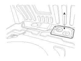
| 3. |
Remove the fuel pump service cover (A) in the trunk.
|
| 4. |
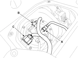
Disconnect the fuel feed tube quick-connector (A). |
| 5. |
Disconnect the fuel tank pressure sensor connector (B). |
| 6. |
Disconnect the fuel pump control module & fuel pump extension connector (C).
|
| 7. |
Lift the vehicle. |
| 8. |
Remove the main muffer. (Refer to Engine Mechanical System - "Muffler") |
| 9. |
Support the fuel tank with a jack. |
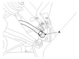
| 10. |
Disconnect the fuel filler hose (A).
|

| 11. |
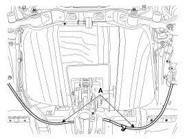
Disconnect the vapor hose quick-connector (A).
|
| 12. |
Remove the parking brake line (A). [NON - EPB type]
|
| 13. |
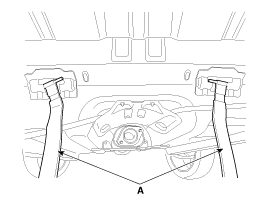
Remove the fuel tank bands (A) installation nuts.
|
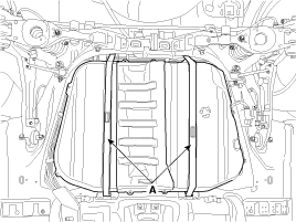
| 14. |
Remove the fuel tank after removing the fuel tank band (A) as below.
|
| Installation |
| 1. |
Install in the reverse order of removal.
|
Fuel Pressure Test (Low pressure system) 1. Release the residual pressure in fuel line. (Refer to the Fuel Delivery System - Repair Procedures - "Release Residual Pressure in Fuel Line").
Inspection [Fuel pump] 1. Turn the ignition switch OFF, and then remove battery (-) cable. 2. Remove the fuel pump assembly. 3. Check that motor operates properly when applying battery voltage to terminals 2 and 4 of fuel pump connector (A).
Other information:
Kia Cadenza YG 2016-2021 Service Manual: Auto defoging sensor Repair procedures
Inspection 1. Press the OFF switch more then 4 times within 2 seconds while pressing the MODE switch. DisplayFail description00Normal23Auto defog sensor OPEN24Auto defog sensor SHORT43Defog door potentiometer OPEN/SHORT44Defog door potentiometer * Diagnostic procedure refer to DTC code.
Kia Cadenza YG 2016-2021 Service Manual: Blower Resistor Repair procedures
Inspection 1. Measure terminal - to - terminal resistance of blower resistor. 2. If measure resistance isnot within specification, the blower resistor must be replaced. Replacement 1. Disconnect the negative (-) battery terminal. 2. Remove the crash pad lower cover (A) and then disconnect the connector (B).
Categories
- Manuals Home
- Kia Cadenza Owners Manual
- Kia Cadenza Service Manual
- Brake System
- Body (Interior and Exterior)
- Steering System
- New on site
- Most important about car
