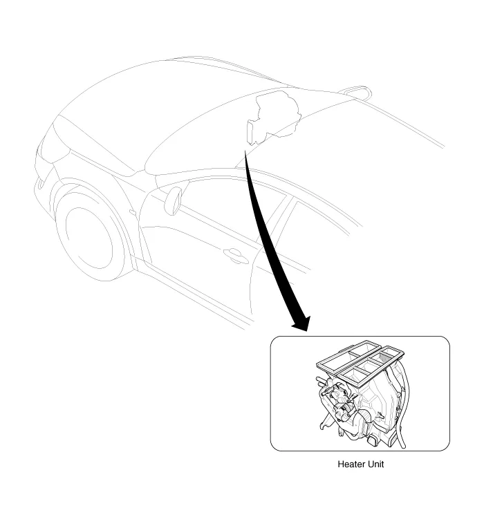
Kia Cadenza YG: Heater / Heater Unit Components and Components Location
Kia Cadenza YG 2016-2021 Service Manual / Heating,Ventilation, Air Conditioning / Heater / Heater Unit Components and Components Location
| Component Location |
| Components |
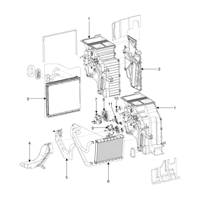
| 1. Heater Case (LH) 2. Separator 3. Evaporator Core 4. Shower Duct (LH) | 5. Heater Core Cover 6. Heater Core 7. Mode Actuator 8. Mode Cam | 9. Temp Actuator (Drive) 10. Vent Door Arm 11. Floor Door Arm |
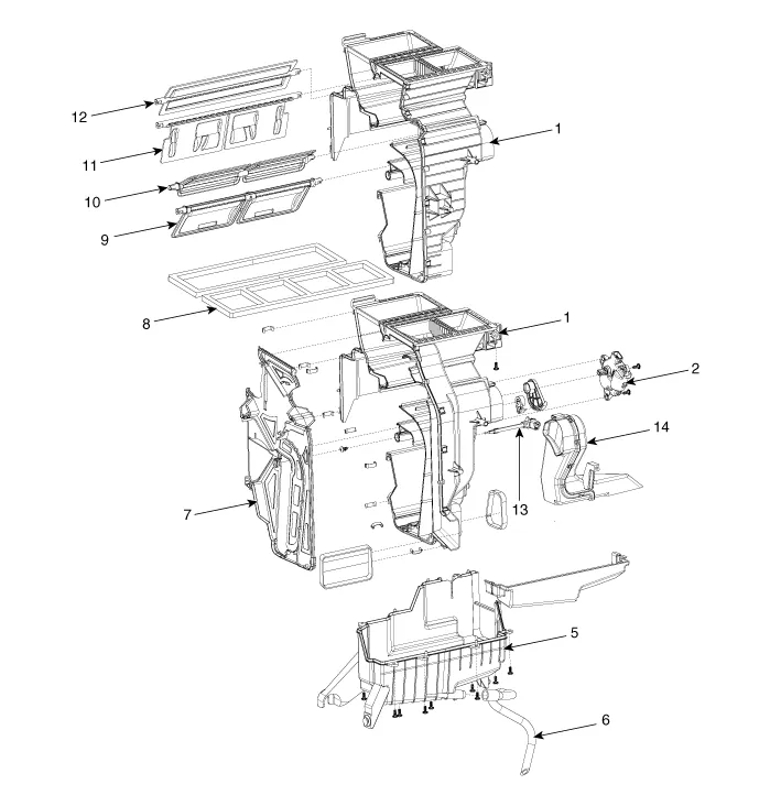
| 1. Heater Case (RH) 2. Temp Actuator (Passenger) 3. Temp Door Lever 4. Evaporator Temp Sensor 5. Hearer Lower Case | 6. Drain Hose 7. Separator 8. Insulator 9. Temp Door 10. Floor Door | 11. Vent Door 12. Def Door 13. Evaporator sensor 14. Shower duct(RH) |
Replacement 1. Disconnect the negative (-) battery terminal. 2. Recover the refrigerant with a recovery/ recycling/ charging station. 3.
Other information:
Kia Cadenza YG 2016-2021 Service Manual: Components and Components Location
C
Kia Cadenza YG 2016-2021 Service Manual: Cluster ionizer Description and Operation
Description 1. The function of cluster ion generator is cleaning air by sterilizing and dissolving of air conditioner. 2. The function of cluster ion generator is controlling mold caused by stench of air conditioner and external inflow of air.
Categories
- Manuals Home
- Kia Cadenza Owners Manual
- Kia Cadenza Service Manual
- Battery Troubleshooting
- Brake System
- Automatic Transaxle System
- New on site
- Most important about car

Copyright © 2026 www.kcadenzavg.com - 0.0218