Kia Cadenza YG: Engine Control System / Fuel Tank Pressure Sensor (FTPS) Repair procedures
Kia Cadenza YG 2016-2021 Service Manual / Engine Control / Fuel System / Engine Control System / Fuel Tank Pressure Sensor (FTPS) Repair procedures
| Inspection |
| 1. |
Connect the GDS on the Data Link Connector (DLC). |
| 2. |
Measure the output voltage of the FTPS.
|
| Removal |
| 1. |
Turn the ignition switch OFF and disconnect the battery negative (-) cable. |
| 2. |
Remove the floor mat in the trunk. |
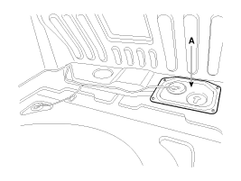
| 3. |
Remove the service cover (A).
|
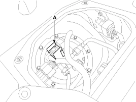
| 4. |
Disconnect the fuel tank pressure sensor connector. |
| 5. |
Remove the fuel tank pressure sensor (A) after releasing the hooks veritically.
|
| Installation |
|

|
| 1. |
Install in the reverse order of removal. |
Circuit Diagram
Description Based on information from various sensors, the ECM can calculate the fuel amount to be injected. The fuel injector is a solenoid-operated valve and the fuel injection amount is controlled by length of injection time.
Other information:
Kia Cadenza YG 2016-2021 Service Manual: Pantoscopic Camera Components and Components Location
C
Kia Cadenza YG 2016-2021 Service Manual: Description and Operation
Description The immobilizer system will disable the vehicle unless the proper ignition key is used, in addition to the currently available anti-theft systems such as car alarms, the immobilizer system aims to drastically reduce the rate of auto theft.
Categories
- Manuals Home
- Kia Cadenza Owners Manual
- Kia Cadenza Service Manual
- Battery Troubleshooting
- Alternator Schematic Diagrams
- Body (Interior and Exterior)
- New on site
- Most important about car

Copyright © 2026 www.kcadenzavg.com - 0.0168