Kia Cadenza YG: Cooling System / Reservoir Tank Repair procedures
Kia Cadenza YG 2016-2021 Service Manual / Engine Mechanical System / Cooling System / Reservoir Tank Repair procedures
| Removal and Installation |
| 1. |
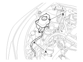
Disconnect the over flow hose (A), and then remove the resorvior tank (B).
|
| 2. |
Installation is in the reverse order of removal. |
| 3. |
Fill the reservoir tank to the "F" line with coolant.
|
Removal and Installaton 1. Remove the engine room under cover. (Refer to Engine And Transaxle Assembly - “Engine Room Under Cover”) 2. Drain the coolant.
Components 1. Water pipe 2. Throttle body coolant hose & pipe3. Water temperature control assembly4. O-ring
Other information:
Kia Cadenza YG 2016-2021 Service Manual: Adaptive Front Lighting System Repair procedures
Removal 1. Disconnect the negative (-) battery terminal. 2. Using a screwdriver or remover, remove the crash pad side cover (A). [RH] 3. Disconnect the stopper (B) from the glove box (A). 4. Disconnect the air damper (A) from the glove box (B).
Kia Cadenza YG 2016-2021 Service Manual: Special Service Tools
S
Categories
- Manuals Home
- Kia Cadenza Owners Manual
- Kia Cadenza Service Manual
- Mode Control Actuator Repair procedures
- Engine Electrical System
- Battery Troubleshooting
- New on site
- Most important about car

Copyright © 2026 www.kcadenzavg.com - 0.0219