Kia Cadenza: Automatic Transaxle Control System / Inhibitor Switch Repair procedures
Kia Cadenza YG 2016-2025 Service Manual / Automatic Transaxle System / Automatic Transaxle Control System / Inhibitor Switch Repair procedures
| Inspection |
|

Power Circuit Inspection
| 1. |
Disconnect the Inhibitor swtich connector. |
| 2. |
Ignition KEY "ON"" & Engine "OFF". |
| 3. |
Measure voltge between supplied power and ground at inhibitor circuit.
|
Signal Circuit Inspection
| 1. |
Connect the Inhibitor switch connector. |
| 2. |
Ignition KEY "ON" & Engine "OFF". |
| 3. |
Measure voltages between each terminal and chassis ground during shift lever changed "P, R, N, D".
Signal Code Table
|
| Removal |
| 1. |
Place the shift lever into the "N" position. |
| 2. |
Remove the air cleaner assembly.
(Refer to Engine Mechanical System - "Air cleaner") |
| 3. |
Remove the battery and the battery tray.
(Refer to Engine Electrical System - "Battery") |
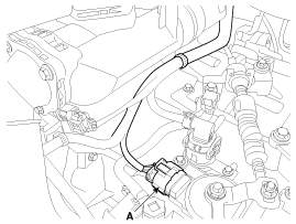
| 4. |
Disconnect the inhibitor switch connector (A).
|
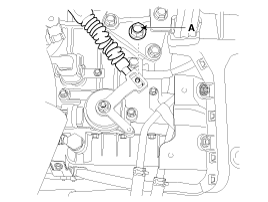
| 5. |
Remove the shift cable mounting nut (A).
|
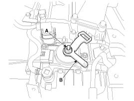
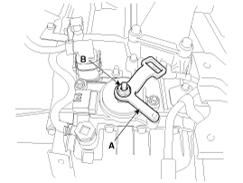
| 6. |
Remove the manual control lever (B) and the washer after removing a nut (A).
|
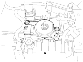
| 7. |
Remove the inhibitor switch (A) after removing the bolts (2ea).
|
| Installation |
| 1. |
Check that the shift lever is placed in the "N" position |
| 2. |
Install the inhibitor switch (A).
|
| 3. |
Install the manual control lever (A).
|
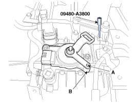
| 4. |
Align the hole (A) in the manual control lever with the "N"
position hole (B) of the inhibitor switch and then insert the SST
inhibitor switch guide pin (09480-A3800).
|
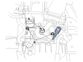
| 5. |
Tighten the nut (A) and bolts (B) with the specified torque.
|
| 6. |
Remove the SST (09480-A3800) from the hole. |
| 7. |
Connect the inhibitor switch connector (A).
|
| 8. |
Install the shift cable by tightening nut (A).
|
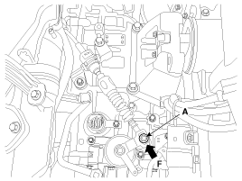
| 9. |
Push the shift cable to the arrow "F" to eliminate free play and then tighten the nut (A) with the specified torque.
|
| 10. |
Install the battery and battery tray.
(Refer to Engine Electrical System - "Battery") |
| 11. |
Install the air cleaner assembly.
(Refer to Engine Mechanical System - "Air cleaner") |
 Inhibitor Switch Schematic Diagrams
Circuit Diagram
...
 Shift Lever Components and Components Location
Components
1. Shift lever knob & Boots assembly2. Shift lever assembly 3. Control cable assembly
...
Other information:
Kia Cadenza YG 2016-2025 Owners Manual: Owner maintenance
The following lists are vehicle checks and inspections that should be performed by the owner or an authorized Kia dealer at the frequencies indicated to help ensure safe, dependable operation of your vehicle. Any adverse conditions should be brought to the attention of your dealer as ...
Kia Cadenza YG 2016-2025 Owners Manual: Compass function
The Compass can be turned ON and OFF, but it returns to ON after the ignition is cycled. 1. Press and release the Control Button within 1 second to turn the display feature OFF. 2. Press and release the Control Button again within 1 second to turn the display back ON. Additional opt ...
Copyright © www.kcadenzavg.com 2017-2025
