Kia Cadenza YG: Automatic Transaxle Control System / Shift Lever Components and Components Location
| Components |
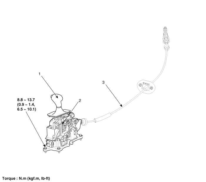
| 1. Shift lever knob & Boots assembly 2. Shift lever assembly | 3. Control cable assembly |
Inspection • Thoroughly check connectors for looseness, poor connection, bending, corrosion, contamination, deterioration, or damage.
Removal 1. Remove the center console assembly. (Refer to Body - "Floor console") 2. Remove the air duct (A). 3. Disconnect the shift cable (A) and then remove the shift cable (B) after pressing the shift cable socket (C) in the direction of "F".
Other information:
Kia Cadenza YG 2016-2021 Service Manual: Surround View Monitoring Switch Repair procedures
Removal 1. Disconnect the negative (-) battery terminal. 2. Remove the floor console upper cover. (Refer to Body - "Floor Console Assembly") 3. Disconnect the console upper cover connector (A). 4. Remove the cup holder assembly (A) after loosening the mounting screws.
Kia Cadenza YG 2016-2021 Service Manual: Refrigerant line Repair procedures
Replacement 1. Discharge refrigerant from refrigeration system. 2. Replace faulty tube or hose. Cap the open fittings immediately to keep moisture or dirt out of the system. 3. Tighten joint of bolt or nut to specified torque.
Categories
- Manuals Home
- Kia Cadenza Owners Manual
- Kia Cadenza Service Manual
- Timing Chain Repair procedures
- Specifications
- Schematic Diagrams
- New on site
- Most important about car
