Kia Cadenza YG: Automatic Transaxle Control System / Shift Lever Repair procedures
Kia Cadenza YG 2016-2021 Service Manual / Automatic Transaxle System / Automatic Transaxle Control System / Shift Lever Repair procedures
| Removal |
| 1. |
Remove the center console assembly.
(Refer to Body - "Floor console") |
| 2. |
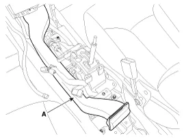
Remove the air duct (A).
|
| 3. |
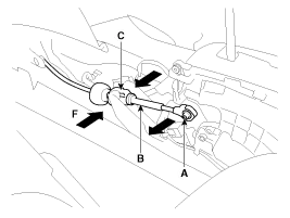
Disconnect the shift cable (A) and then remove the shift
cable (B) after pressing the shift cable socket (C) in the direction of
"F".
|

| 4. |
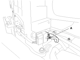
Shift lever assembly connector (A).
|
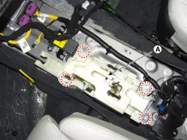
| 5. |
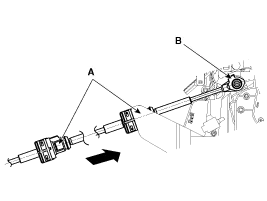
Remove the shift lever assembly (A) by removing the bolts (4ea).
|
| Inspection |
| 1. |
Check the damage and operation of the control cable. |
| 2. |
Check the damage of the boot. |
| 3. |
Check the damage and corrosion of the bushing. |
| 4. |
Check the damage or weakening of the spring. |
| Installation |
| 1. |
Installation is the reverse of removal.
|

Components 1. Shift lever knob & Boots assembly2. Shift lever assembly 3. Control cable assembly
Components 1. Shift lever knob & Boots assembly2. Shift lever assembly3. Control cable assembly
Other information:
Kia Cadenza YG 2016-2021 Service Manual: Specifications
Specification Air Conditioner ItemSpecificationCompressorType6VSX16Oil type & CapacityPAG OIL 100±10Pulley type6PK-TYPEDisplacement160cc/revCondenserHeat rejection14,400 ±5% kcal/hrA/C Pressure transducerThe method to measure the pressureVoltage= 0.
Kia Cadenza YG 2016-2021 Service Manual: Compressor Components and Components Location
C
Categories
- Manuals Home
- Kia Cadenza Owners Manual
- Kia Cadenza Service Manual
- Automatic Transaxle System
- Body Electrical System
- Battery Troubleshooting
- New on site
- Most important about car

Copyright © 2026 www.kcadenzavg.com - 0.0276