Kia Cadenza YG: Brake System / Brake Pedal Repair procedures
| Removal |
| 1. |
Remove the crash pad lower panel. (Refer to the Body group- crash pad). |
| 2. |
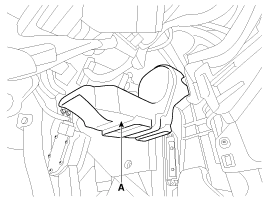
Remove the shower duct (A).
|
| 3. |
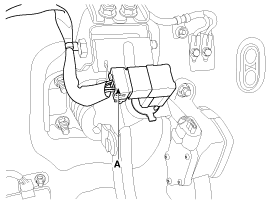
Disconnect the stop lamp switch connector (A).
|
| 4. |
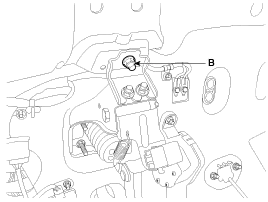
Remove the brake pedal member mounting nut (B).
|
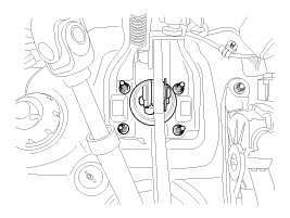
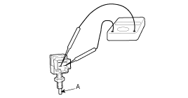
| 5. |
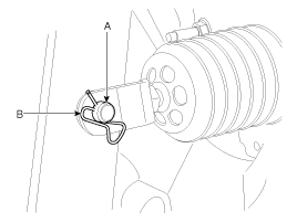
Remove the snap pin (A) and clevis pin (B).
|
| 6. |
Remove the brake pedal member assembly mounting nuts and then remove the brake pedal assembly.
|
| Inspection |
| 1. |
Check the bushing for wear. |
| 2. |
Check the brake pedal for bending or twisting. |
| 3. |
Check the brake pedal return spring for damage. |
| 4. |
Check the stop lamp switch.
|
| Adjustment |
| Stop lamp switch clearance adjustment |
| 1. |
Remove the shower duct (A).
|
| 2. |
Disconnect the stop lamp switch connector (A).
|
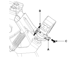
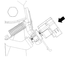
| 3. |
Release locking plate by pushing the hooks (B) carefully, and then pull the locking plate (A) as indicated by the arrow (C).
|
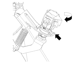
| 4. |
Turn stop lamp switch 45° counterclockwise and remove it.
|
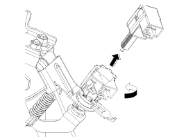
| 5. |
Fix the brake pedal arm and insert fully the stop lamp switch as hiding contact part.
|
| 6. |
After inserting, turn the stop switch (A) 45° clockwise, and then assemble locking plate (B) by pushing.
|
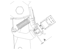
| 7. |
Confirm the gap between stop lamp switch and bracket.
|
| 8. |
Connect the stop lamp switch connector. |
| 9. |
Install the shower duct (A).
|
| Installation |
| 1. |
Installation is the reverse of removal.
|

| 2. |
Adjust the brake pedal height and free play. |
| 3. |
Check the brake pedal operation. |
Components 1. Cowl bracket2. Brake pedal member assembly3. Stop lamp switch4. Return spring5. Brake pedal stopper6. Clevis pin7. Snap pin8. Brake pedal
Components 1. Guide rod bolt2. Bleed screw3. Caliper carrier4. Caliper body5. Inner pad shim6. Brake pad7. Pad retainer
Other information:
Kia Cadenza YG 2016-2021 Service Manual: Pantoscopic Camera Repair procedures
Removal Front Pantoscopic Camera 1. Disconnect the negative (-) battery terminal. 2. Remove the front bumper cover. (Refer to Body - "Front Bumper Cover") 3. Remove the pantocscpic camera (B) after loosening the mounting screws and connector (A).
Kia Cadenza YG 2016-2021 Service Manual: Description and Operation
Description The immobilizer system will disable the vehicle unless the proper ignition key is used, in addition to the currently available anti-theft systems such as car alarms, the immobilizer system aims to drastically reduce the rate of auto theft.
Categories
- Manuals Home
- Kia Cadenza Owners Manual
- Kia Cadenza Service Manual
- Restraint
- Specifications
- Brake System
- New on site
- Most important about car
