Kia Cadenza YG: Brake System / Front Disc Brake Components and Components Location
Kia Cadenza YG 2016-2021 Service Manual / Brake System / Brake System / Front Disc Brake Components and Components Location
| Components |
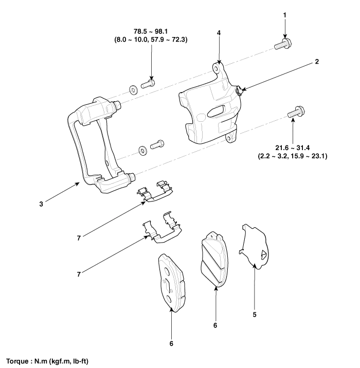
| 1. Guide rod bolt 2. Bleed screw 3. Caliper carrier 4. Caliper body | 5. Inner pad shim 6. Brake pad 7. Pad retainer |
Removal 1. Remove the crash pad lower panel. (Refer to the Body group- crash pad). 2. Remove the shower duct (A). 3. Disconnect the stop lamp switch connector (A).
Removal 1. Remove the front wheel & tire. Tightening torque: 88.3 ~107.9 N.m (9.0 ~11.0 kgf.m, 65.1 ~79.6 lb-ft) 2. Loosen the hose eyebolt (C) and caliper mounting bolts (B), then remove the front caliper assembly (A).
Other information:
Kia Cadenza YG 2016-2021 Service Manual: Blind Spot Detection Switch Repair procedures
Removal 1. Disconnect the negative (-) battery terminal. 2. Remove the passenger compartment junction box cover. 3. Remove the driver side cover (A). 4. Remove the crash pad side switch assembly (A) by pushing it through side cover hole.
Kia Cadenza YG 2016-2021 Service Manual: Intake Actuator Description and Operation
D
Categories
- Manuals Home
- Kia Cadenza Owners Manual
- Kia Cadenza Service Manual
- Timing Chain Repair procedures
- Brake System
- Rail Pressure Sensor (RPS) Schematic Diagrams
- New on site
- Most important about car

Copyright © 2026 www.kcadenzavg.com - 0.0199