Kia Cadenza YG: Engine Control System / Canister Close Valve (CCV) Repair procedures
Kia Cadenza YG 2016-2021 Service Manual / Engine Control / Fuel System / Engine Control System / Canister Close Valve (CCV) Repair procedures
| Inspection |
| 1. |
Turn the ignition switch OFF. |
| 2. |
Disconnect the CCV connector. |
| 3. |
Measure resistance between the CCV terminal 1 and 2. |
| 4. |
Check that the resistance is within the specification.
|
| 5. |
Disconnect the vapor hose connected with the canister from the CCV. |
| 6. |
Connect a vacuum pump to the nipple. |
| 7. |
Ground the CCV control line and apply battery voltage to the CCV power supply line. |
| 8. |
Apply vacuum and check the valve operation.
|
| Removal |
| 1. |
Turn the ignition switch OFF and disconnect the battery negative (-) cable. |
| 2. |
Lift the vehicle. |
| 3. |
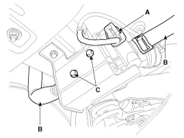
Disconnect the canister close valve connector (A). |
| 4. |
Disconnect the ventilation hose (B) from the fuel tank air filter and canister close valve. |
| 5. |
Remove the fuel tank air filter assembly after removing bolts (C).
|
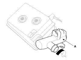
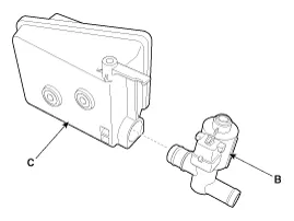
| 6. |
Release the lever (A), and then separate the canister close
valve (B) from the fuel tank air filter (C) after rotating it in the
direction of the arrow in the figure.
|
| Installation |
| • |
Install the component with the specified torques. |
| • |
Note that internal damage may occur when the component is dropped. In this case, use it after inspecting. |
| 1. |
Install in the reverse order of removal. |
Circuit Diagram
Other information:
Kia Cadenza YG 2016-2021 Service Manual: Blower Unit Repair procedures
Replacement 1. Disconnect the negative (-) battery terminal. 2. Remove the heater and blower unit.(Refer to HA group – heater unit). 3. Remove the blower unit (A) from the heater unit after loosening a mounting bolt and 3 screws. Make sure that there is no air leaking out of the blower and duct joints.
Kia Cadenza YG 2016-2021 Service Manual: Intake Actuator Repair procedures
Inspection 1. Ignition "OFF". 2. Disconnect the intake actuator connector. 3. Verify that the actuator operates to the recirculation position when connecting 12V to the terminal 3 and grounding terminal 7. 4. Verify that the intake actuator operates to the fresh position when connecting in the reverse.
Categories
- Manuals Home
- Kia Cadenza Owners Manual
- Kia Cadenza Service Manual
- Rail Pressure Sensor (RPS) Schematic Diagrams
- Transaxle Control Module (TCM) Repair procedures
- Brake System
- New on site
- Most important about car

Copyright © 2026 www.kcadenzavg.com - 0.0248