Kia Cadenza YG: Cylinder Block / Crankshaft Repair procedures
| Disassembly |
|

|

| 1. |
Remove the engine assembly from the vehicle.
(Refer to Engine And Transmission Assembly - "Engine And Transmission Assembly") |
| 2. |
Remove the transaxle assembly from the engine assembly.
(Refer to Automatic Transaxle System - "Automatic Transaxle") |
| 3. |
Remove the drive plate and adapter plate.
(Refer to Cylinder Block - "Drive Plate") |
| 4. |
Remove the rear oil seal case.
(Refer to Cylinder Block - "Rear Oil Seal") |
| 5. |
Install the engine assembly to engine stand for disassembly. |
| 6. |
Remove the exhaust manifold.
(Refer to Intake And Exhaust System - "Exhaust Manifold") |
| 7. |
Remove the intake manifold.
(Refer to Intake And Exhaust System - "Intake Manifold") |
| 8. |
Remove the timing chain.
(Refer to Timing System - "Timing Chain") |
| 9. |
Remove the water temperature control assembly.
(Refer to Cooling System - "Water Temperature Control Aassembly") |
| 10. |
Remove the cylinder head.
(Refer to Cylinder Head Assembly - "Cylinder Head") |
| 11. |
Remove the oil pump.
(Refer to Lubrication System - "Oil Pump") |
| 12. |
Remove the oil filter body.
(Refer to Lubrication System - "Oil filter body") |
| 13. |
Remove the upper oil pan.
(Refer to Lubrication System - "Oil Pan") |
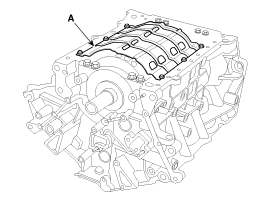
| 14. |
Remove the baffle plate (A).
|
| 15. |
Check the connecting rod end play.
(Refer to Cylinder Block - "Piston and Connecting Rod") |
| 16. |
Check the connecting rod cap oil clearance.
(Refer to Cylinder Block - "Piston and Connecting Rod") |
| 17. |
Remove the piston and connecting rod assemblies.
(Refer to Cylinder Block - "Piston and Connecting Rod") |
| 18. |
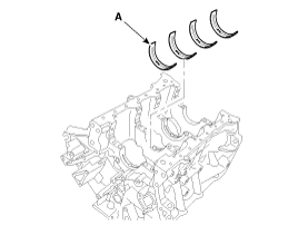
Remove the crankshaft main bearing cap and check oil clearance. |
| 19. |
Check the crankshaft end play. |
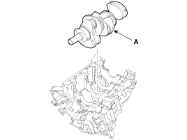
| 20. |
Remove the crankshaft. Lift the crankshaft (A) out of engine, being careful not to damage journals.
|
| Inspection |
| 1. |
Check the crankshaft bearing oil clearance.
| |||||||||||||||||||||||||||||||||||||||||||||||||||||||||||||||||||||||||||||||||||||||||||||||||||

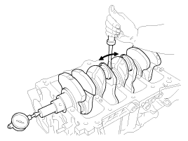
| 2. |
Check crankshaft end play.
Using a dial indicator, measure the thrust clearance while prying the crankshaft back and forth with a screwdriver.
If the end play is greater than maximum, replace the thrust bearings as a set.
|
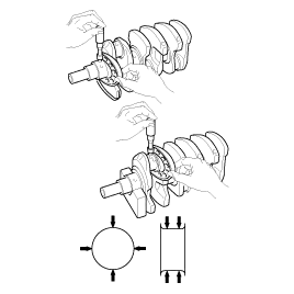
| 3. |
Inspect main journals and crank pins
Using a micrometer, measure the diameter of each main journal and crank pin.
|
| Reassembly |
|
| 1. |
Install the main bearings.
|
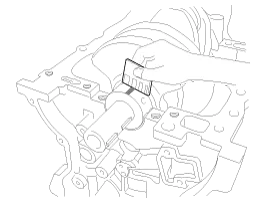
| 2. |
Install the thrust bearings.
Install the 2 thrust bearings(A) under the No.3 journal position of the cylinder block with the oil grooves facing outward.
|

| 3. |
Place the crankshaft(A) on the cylinder block.
|
| 4. |
Place the main bearing caps on cylinder block. |
| 5. |
Install the main bearing cap bolts.
|

| 6. |
Check crankshaft end play. |
| 7. |
Install the piston and connecting rod assemblies.
(Refer to Cylinder Block - "Piston and Connecting Rod") |
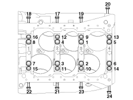
| 8. |
Install the baffle plate.
Install and uniformly tighten the baffle plate bolts, in several passes, in the sequence shown.
|

| 9. |
Assemble the other parts in the reverse order of disassembly.
|
Components 1. Crank shaft upper bearing2. Thrust bearing3. Crankshaft4. Crankshaft lower bearing5. Main bearing cap
Disassembly • Use fender covers to avoid damaging painted surfaces. • To avoid damage, unplug the wiring connectors carefully while holding the connector portion.
Other information:
Kia Cadenza YG 2016-2021 Service Manual: Description and Operation
Description System Operation Typically, lane departure warning is activated at a speed over 70 KPH, but suppressed in case of unintentional lane departure when driver do not operate turn signal. System Operation Conditions 1. User Conditions (1) When unintended lane departure is occured, warnings are generated.
Kia Cadenza YG 2016-2021 Service Manual: Cluster ionizer Description and Operation
Description 1. The function of cluster ion generator is cleaning air by sterilizing and dissolving of air conditioner. 2. The function of cluster ion generator is controlling mold caused by stench of air conditioner and external inflow of air.
Categories
- Manuals Home
- Kia Cadenza Owners Manual
- Kia Cadenza Service Manual
- Body (Interior and Exterior)
- Steering System
- Brake System
- New on site
- Most important about car
