Kia Cadenza YG: Surround View Monitoring (SVM) System / Description and Operation
| Description |
| Major Features |
| 1. |
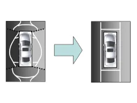
Display Vehicles Surrounding in Video
The surrounding area video display function displays the 360
degrees video image captured through 4 cameras to the driver through the
Head Unit Screen while the vehicle is moving at low speed or going
reverse. The SVM System displays total of 8 video modes for displaying
surrounding video based on the vehicle driving state and the driver''s
selection. |
| 2. |
Guide Line Indication & Steering Wheel Synchronized Feature
The Guide Line Indication & Steering Wheel Synchronized
Feature is the function that assists the driver in parking by
synchronizing the steering wheel with the rear view video display marked
with a guide line to help anticipate the direction of the vehicle going
reverse. |
| 3. |
Front/Rear Object Warning (Obstacle Detection Feature)
The system receives obstacle warning signal from the PAS or
SPAS sensors mounted on the front/rear of the vehicle and displays the
obstacle location on the AVM Head Unit Screen. |
| 4. |
Tolerance Compensation (including A/S)
Manual Tolerance Compensation Software is embedded in the SVM
ECM to compensate the SVM deviation that may occur due to assembly line
installation tolerance. You must first setup proper work environment in
order to perform correct tolerance compensation. |
| No. | Main Features | Detailed Description | Notes | ||||||
| 1 | 8 View Mode Display |
| Merged Video Display of 8 Modes | ||||||
| 2 | Front Assist Mode Selection Feature |
| Same as the PAS AVM Switch | ||||||
| 3 | Rear Steering Synchronized Parking Guide Line Display |
| Display over the Rear Video | ||||||
| 4 | PAS Obstacle Indication |
| Display both on the Cluster and the Head Unit | ||||||
| 5 | User Setting Option |
| Provides additional screen settings | ||||||
| 6 | Assembly Line & A/S Tolerance Compensation Feature |
| Compensation function recognition logic applied |
| 1. |
Front View Mode
|
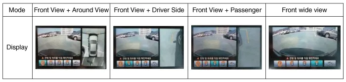
| 2. |
Rear View Mode
|

| – |
Initial Entry: When the rear and front mode view in SVM mode is displayed on the screen for the first time |
| – |
Re-entry: When switching from SVM mode to another mode, without turning off SVM, and returning to the previous mode
(e.g. Rear → Front → Rear: Re-enter rear mode / Front → Rear → Front: Re-enter front mode) |
| Switch mode | Vehicle speed | Gear | SVM Switch | Display view |
| Rear → Front | below 20 kph | R Range or P Range excluded | ON | Initial Entry: Front view set in the initial view mode option |
| Re-entry: The last view mode displayed in the previous front mode | ||||
| Front → Rear | Irrelevant | Reverse Gear | Irrelevant | Initial Entry: Rear view set in the initial view mode option |
| Re-entry: The last view mode displayed in the previous rear mode |
| OFF Mode | Vehicle speed | Gear | SVM Switch | Notes |
| Front mode | over 20 kph | R Range or P Range | OFF | If any of the three conditions are satisfied |
| Rear mode | Irrelevant | Except R gear | Irrelevant | If any of the two conditions are satisfied |
| Option | Function | Default setting |
| Guideline steering interlocking | Interlocks with steering to display the driving direction of the vehicle during parking. | Classification code |
| Close range warning indicator | Indicates front and rear obstacle detection | Classification code |
| Initial view mode setting | Default view displayed when entering SVM mode | Front + around view |
| Rear + around view |
| 1. |
View modes for guideline steering interlocking indications
|


| 2. |
Specifications for guideline steering interlocking trace lines
|


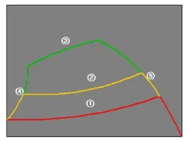
| 3. |
Indications for neutral trace lines
If the steering angle is neutral, the neutral trace line is
indicated in blue, which shows the expected movement trace of the car.
This line is displayed with the guideline steering
interlocking trace line and is also a fixed line that is not interlocked
with the steering angle operation. |
Components Component Functions No.ComponentsQuantityMajor Role1SVM Unit1 – Input video information from 4 channel cameras and process display – Vehicle communication (CAN) and system control – Screen output in 8 view modes 2Ultra optical camera(190 degrees)4 – Record vehicle''s surrounding area 3AVN Head Unit1 – Provide driver with video via SVM ECM output – Send user input data to SVM ECM 4SVM Switch1 – Input video feed in Front Mode
Circuit Diagram SVM System Input/Output 1. Camera input ItemSpecificationLens angle of view190 degreesAngle of viewHorizontal186 degreesVertical135 degreesFunctionProvides the original image of the wide angle image (no additional function)Application locationSame camera applied to the front, rear, left and right 2.
Other information:
Kia Cadenza YG 2016-2021 Service Manual: Description and Operation
Description Adaptive Front-lighting System (AFLS) AFLS(Adaptive Front-lighting System)is a headlamp orientation control system that takes into account both steering angle and vehicle speed to orient the headlamps to an angle that provides better nighttime visibility.
Kia Cadenza YG 2016-2021 Service Manual: Description and Operation
System Overview RPAS (Rear Parking Assist System) is an electronic driving aid that warns the driver to be cautious while parking or in low speed environments. The sensor uses ultrasonic waves to detect objects within proximity of the vehicle.
Categories
- Manuals Home
- Kia Cadenza Owners Manual
- Kia Cadenza Service Manual
- Schematic Diagrams
- Automatic Transaxle System
- Timing Chain Repair procedures
- New on site
- Most important about car
