Kia Cadenza YG: Surround View Monitoring (SVM) System / Schematic Diagrams
| Circuit Diagram |
| 1. |
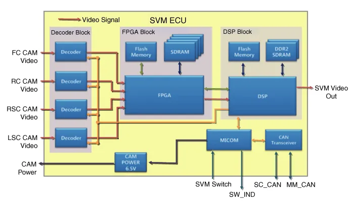
Camera input
| |||||||||||||||||
| 2. |
SVM image output
The SVM unit carries out distortion compensation and video
merging on the image from 4 cameras installed around the vehicle,
indicates steering interlocking guidelines and others, and outputs them
in analog. |
| 3. |
SVM switch
When the switch is ON, this is used as a control input signal that operates the front view mode. |
| 4. |
Ignition input
The SVM unit outputs images only when IGN2 ON. When IGN2 OFF , it is an SVM OFF state, and limits image outputting.
SVM unit uses signals inputted through IGN pin or M_CAN communication to determine whether IGN2 is ON or OFF. |
| 5. |
Output switch indicator lamp
SVM units output power through PWM waves from the LED located
in the SVM switch to show the user whether the switch has been pressed.
|
| 6. |
Input chassis CAN (C_CAN)
The SVM unit uses C_CAN to receive information about the
vehicle''s condition and to decide whether to carry out main SVM
operations. |
| 7. |
Multimedia CAN input/output (M_CAN)
The SVM unit uses the AVN, which displays images from the
SVM, and M_CAN to communicate to send and receive the following
information.
|
Description Surround View Monitoring System (SVM) is the system that allows video monitoring of 360 degrees around the vehicle. The system includes 4 ultra optical camera mounted around the vehicle (front, both sides, rear).
Inspection Tolerance Calibration Tolerance calibration compensates for the error margins of surround view video that occur due to the installation tolerance when the four cameras that comprise the SVM system are installed.
Other information:
Kia Cadenza YG 2016-2021 Service Manual: A/C Pressure Transducer Description and Operation
Description A/C pressure transducer convert the pressure value of high pressure line into voltage value after measure it. By converted voltage value, engine ECU controls cooling fan by operating it high speed or low speed. Engine ECU stop the operation of compressor when the temperature of refrigerant line is so high or so low irregularl
Kia Cadenza YG 2016-2021 Service Manual: Blower Motor Repair procedures
Inspection 1. Connect the battery voltage and check the blower motor rotation. 2. If the blower motor voltage is not operated well, substitute with a known-good blower motor and check for proper operation. 3. If the problem is corrected, replace the blower motor.
Categories
- Manuals Home
- Kia Cadenza Owners Manual
- Kia Cadenza Service Manual
- Body (Interior and Exterior)
- Steering System
- Engine Electrical System
- New on site
- Most important about car
