Kia Cadenza YG: Cylinder Block / Cylinder Block Repair procedures
| Disassembly |
|

|

| 1. |
Remove the engine assembly from the vehicle.
(Refer to Engine And Transmission Assembly - "Engine And Transmission Assembly") |
| 2. |
Remove the transaxle assembly from the engine assembly.
(Refer to Automatic Transaxle System - "Automatic Transaxle") |
| 3. |
Remove the drive plate and adapter plate.
(Refer to Cylinder Block - "Drive Plate") |
| 4. |
Remove the rear oil seal case.
(Refer to Cylinder Bolck - "Rear Oil Seal") |
| 5. |
Install the engine to engine stand for disassembly. |
| 6. |
Remove the exhaust manifold.
(Refer to Intake And Exhaust System - "Exhaust Manifold") |
| 7. |
Remove the intake manifold.
(Refer to Intake And Exhaust System - "Intake Manifold") |
| 8. |
Remove the timing chain.
(Refer to Timing System - "Timing Chain") |
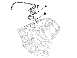
| 9. |
Remove the water temperature control assembly.
(Refer to Cooling System - "Water Temperature Control Aassembly") |
| 10. |
Remove the cylinder head.
(Refer to Cylinder Head Assembly - "Cylinder Head") |
| 11. |
Remove the oil pump.
(Refer to Lubrication System - "Oil Pump") |
| 12. |
Remove the oil filter body.
(Refer to Lubrication System - "Oil filter body") |
| 13. |
Remove the oil cover (A) and gasket (B).
|
| 14. |
Remove the water jacket seperator.
(Refer to Cylinder Block - "Water Jacket Seperator") |
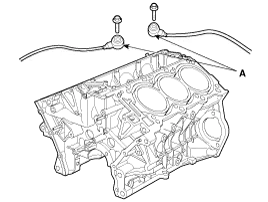
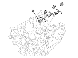
| 15. |
Remove the knock sensor (A).
|
| 16. |
Remove the upper oil pan.
(Refer to Lubrication System - "Oil Pan") |
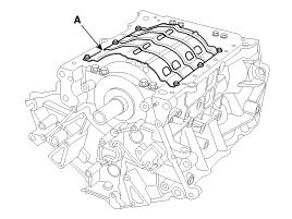
| 17. |
Remove the baffle plate (A).
|
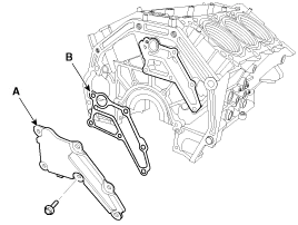
| 18. |
Remove the oil drain cover (A) and gasket (B).
|
| 19. |
Check the connecting rod end play.
(Refer to Cylinder Block - "Piston and Connecting Rod") |
| 20. |
Check the connecting rod cap oil clearance.
(Refer to Cylinder Block - "Piston and Connecting Rod") |
| 21. |
Remove the piston and connecting rod assemblies.
(Refer to Cylinder Block - "Piston and Connecting Rod") |
| 22. |
Remove the crankshaft main bearing cap and check oil clearance.
(Refer to Cylinder Block - "Crankshaft") |
| 23. |
Check the crankshaft end play.
(Refer to Cylinder Block - "Crankshaft") |
| 24. |
Remove the crankshaft.
(Refer to Cylinder Block - "Crankshaft") |
| 25. |
Remove the oil jets (A).
|
| Inspection |
| 1. |
Remove the gasket material.
Using a gasket scraper, remove all the gasket material from the top surface of the cylinder block. |
| 2. |
Clean the cylinder block
Using a soft brush and solvent, thoroughly clean the cylinder block. |
| 3. |
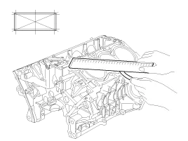
Inspect the top surface of the cylinder block for flatness.
Using a precision straight edge and feeler gauge, measure the surface contacting the cylinder head gasket for warpage.
|
| 4. |
Inspect cylinder bore diameter
Visually check the cylinder for vertical scratchs.
If deep scratches are present, replace the cylinder block. |
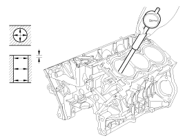
| 5. |
Inspect cylinder bore diameter
Using a cylinder bore gauge, measure the cylinder bore diameter at position in the thrust and axial directions.
|
| 6. |
Check the cylinder bore size code on the cylinder block.
|
| 1. |
Oversize pistons should be selected according to the largest bore cylinder.
|
| 2. |
Measure the outside diameter of the piston to be used. |
| 3. |
According to the measured O.D(Outer Diameter), calculate the new bore size.
|
| 4. |
Bore each of the cylinders to the calculated size.
|
| 5. |
Hone the cylinders, finishing them to the proper dimension (piston outside diameter + gap with cylinder). |
| 6. |
Check the clearance between the piston and cylinder.
|
| Reassembly |
| 1. |
Install the oil jets (A).
|
| 2. |
Install the crankshaft.
(Refer to Cylinder Block - "Crankshaft") |
| 3. |
Install the crankshaft main bearing cap and check oil clearance.
(Refer to Cylinder Block - "Crankshaft") |
| 4. |
Check the crankshaft end play.
(Refer to Cylinder Block - "Crankshaft") |
| 5. |
Install the piston and connecting rod assemblies.
(Refer to Cylinder Block - "Piston and Connecting Rod") |
| 6. |
Check the connecting rod end play.
(Refer to Cylinder Block - Piston and Connecting Rod") |
| 7. |
Install the oil drain cover(A) with a new gasket (B).
|
| 8. |
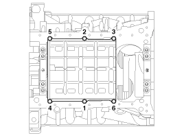
Install the baffle plate.
Install and uniformly tighten the baffle plate bolts, in several passes, in the sequence shown.
|
| 9. |
Install the upper oil pan.
(Refer to Lubrication System - "Oil Pan") |
| 10. |
Install the knock sensor (A).
|
| 11. |
Install the water jacket seperator.
(Refer to Cylinder Block - "Water Jacket Seperator") |
| 12. |
Remove the oil cover (A) and gasket (B).
|
| 13. |
Assemble the other parts in the reverse order of disassembly.
|
Disassembly • Use fender covers to avoid damaging painted surfaces. • To avoid damage, unplug the wiring connectors carefully while holding the connector portion.
Other information:
Kia Cadenza YG 2016-2021 Service Manual: Repair procedures
Inspection Initialization and diagnosis sequence by using diagnostic equipment Below content summarize the procedure for A/S using Diagnostic equipment Download Parameter 1. Select "AFLS" menu after selecting a vehicle. 2. Select "Parameter download" menu for define a characteristc of vehicle.
Kia Cadenza YG 2016-2021 Service Manual: Cluster ionizer Repair procedures
Inspection 1. Press the OFF switch more then 4 times within 2 seconds while pressing the MODE switch. DisplayFail description00Normal50Cluster ionizer fault * Diagnostic procedure refer to DTC code. Replacement 1. Disconnect the negative (-) battery terminal.
Categories
- Manuals Home
- Kia Cadenza Owners Manual
- Kia Cadenza Service Manual
- Timing Chain Repair procedures
- Body Electrical System
- Engine Electrical System
- New on site
- Most important about car
