Kia Cadenza YG: Exhaust Emission Control System / CVVT (Continuously Variable Valve Timing) System Description and Operation
Kia Cadenza YG 2016-2021 Service Manual / Emission Control System / Exhaust Emission Control System / CVVT (Continuously Variable Valve Timing) System Description and Operation
| Description |
Continuous Variable Valve Timing (CVVT) system advances or
retards the valve timing of the intake and exhaust valve in accordance
with the ECM control signal which is calculated by the engine speed and
load.
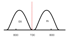
By controlling CVVT, the valve over-lap or under-lap occurs,
which makes better fuel economy and reduces exhaust gases (NOx, HC).
CVVT improves engine performance through reduction of pump loss,
internal EGR effect, improvement of combustion stability, improvement of
volumetric efficiency, and increase of expansion work.
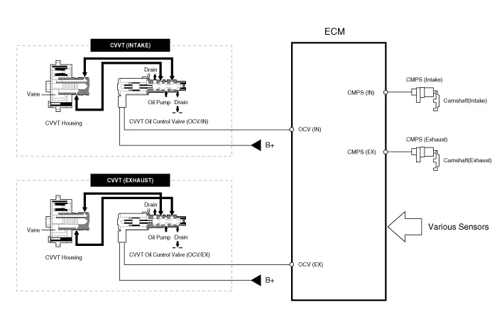
This system consist of
| – |
the CVVT Oil Control Valve (OCV) which supplies the engine
oil to the cam phaser or runs out the engine oil from the cam phaser in
accordance with the ECM PWM (Pulse With Modulation) control signal, |
| – |
the CVVT Oil Temperature Sensor (OTS) which measures the engine oil temperature, |
| – |
and the Cam Phaser which varies the cam phase by using the hydraulic force of the engine oil. |
The engine oil getting out of the CVVT oil control valve
varies the cam phase in the direction (Intake Advance/Exhaust Retard) or
opposite direction (Intake Retard/Exhaust Advance) of the engine
rotation by rotating the rotor connected with the camshaft inside the
cam phaser.
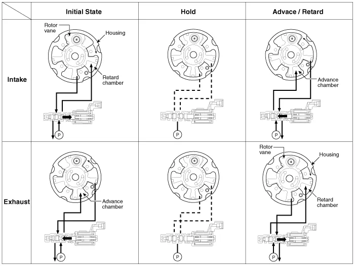
| Operation Principle |
The CVVT has the mechanism rotating the rotor vane with
hydraulic force generated by the engine oil supplied to the advance or
retard chamber in accordance with the CVVT oil control valve control.
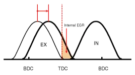
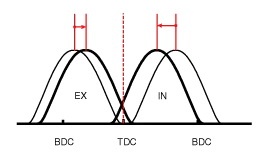
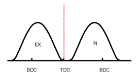
| [CVVT System Mode] |
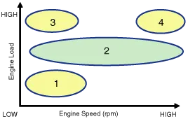
| (1) Low Speed / Low Load | (2) Part Load |
|
|
| (3) Low Speed / High Load | (4) High Speed / High Load |
|
|
| Driving Condition | Exhaust Valve | Intake Valve | ||
| Valve Timing | Effect | Valve Timing | Effect | |
| (1) Low Speed /Low Load | Completely Advance | * Valve Under-lap * Improvement of combustion stability | Completely Retard | * Valve Under-lap * Improvement of combustion stability |
| (2) Part Load | Retard | * Increase of expansion work * Reduction of pumping loss * Reduction of HC | Retard | * Reduction of pumping loss |
| (3) Low Speed /High Load | Retard | * Increase of expansion work | Advance | * Prevention of intake back flow (Improvement of volumetric efficiency) |
| (4) High Speed /High Load | Advance | * Reduction of pumping loss | Retard | * Improvement of volumetric efficiency |
Removal [Catalytic Converter (WCC)] 1. Remove the exhaust manifold. (Refer to Engine Mechanical System - "Exhaust Manifold") [Catalytic Converter (UCC)] 1.
Other information:
Kia Cadenza YG 2016-2021 Service Manual: Repair procedures
Removal 1. Remove the trunk trim in the trunk after removing the screws and clips. (Refer to Body - "Trunk") 2. Remove the camera holder (A) as shown arrow direction, and then remove the back view camera (B). Installation 1. Install the back view camera and camera holder.
Kia Cadenza YG 2016-2021 Service Manual: Troubleshooting
Troubleshooting Problem Symptoms Table Before replacing or repairing air conditioning components, first determine if the malfunction is due to the refrigerant charge, air flow or compressor. Use the table below to help you find the cause of the problem.
Categories
- Manuals Home
- Kia Cadenza Owners Manual
- Kia Cadenza Service Manual
- Timing Chain Repair procedures
- Schematic Diagrams
- Brake System
- New on site
- Most important about car

Copyright © 2026 www.kcadenzavg.com - 0.0209