Kia Cadenza YG: Fuel Delivery System / Fuel Pump Control Module (FPCM) Schematic Diagrams
| Circuit Diagram |
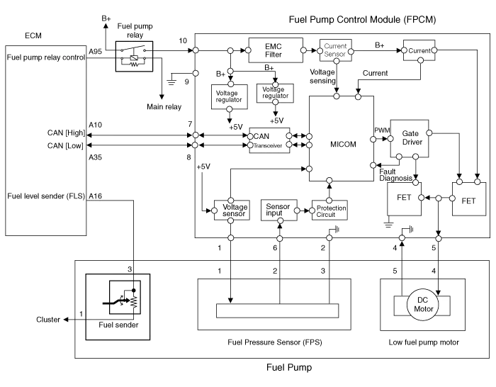
| Fuel Pressure Control Module (FPCM) Terminal And Input/Output signal |

| Pin No. | Description | Connected to |
| 1 | Fuel pressure sensor (FPS) power supply (+5V) | Fuel Pressure Sensor (FPS) |
| 2 | Fuel Pressure Sensor (FPS) Ground (-) | Fuel Pressure Sensor (FPS) |
| 3 | - | |
| 4 | Fuel pump DC motor (-) | Fuel Pump Motor |
| 5 | Fuel pump DC motor (+) | Fuel Pump Motor |
| 6 | Fuel pressure sensor (FPS) signal input | Fuel pressure sensor (FPS) |
| 7 | CAN [High] | ECM |
| 8 | CAN [Low] | ECM |
| 9 | Ground | Chassis Ground |
| 10 | Battery power (B+) | Fuel Pump Relay |
Specification ItemsSpecificationApplied Voltate (V)6~18Current Consumption (A)Max. 15Fuel Pressure StartMax. 600 KPa (Max. 6.1 kgf/cm², Max.
Removal 1. Turn the ignition switch OFF and disconnect the battery negative (-) cable. 2. Lift the vehicle. 3. Remove the fuel pump control module mounting bolts (A).
Other information:
Kia Cadenza YG 2016-2021 Service Manual: Blind Spot Detection Variant Coding Description and Operation
Description The used radar frequency of BSD is two, "North America region" and "Except North America region". If it replaces BSD unit, BSD unit has to perform the procedure of variant coding. BSD Variant Coding 1. Select the "BSD Variant Coding" procedure in BSD system.
Kia Cadenza YG 2016-2021 Service Manual: Auto defoging actuator Repair procedures
Inspection 1. Ignition "OFF”. 2. Disconnect the connector of auto defog control actuator. 3. Verify that the auto defog control actuator operates to the defrost ON mode when connecting 12V to the terminal 3 and grounding terminal 7. 4.
Categories
- Manuals Home
- Kia Cadenza Owners Manual
- Kia Cadenza Service Manual
- Specifications
- Transaxle Control Module (TCM) Repair procedures
- Schematic Diagrams
- New on site
- Most important about car
