Kia Cadenza YG: Fuel Delivery System / Fuel Pump Control Module (FPCM) Repair procedures
| Removal |
| 1. |
Turn the ignition switch OFF and disconnect the battery negative (-) cable. |
| 2. |
Lift the vehicle. |
| 3. |
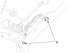
Remove the fuel pump control module mounting bolts (A).
|
| 4. |
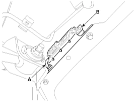
Disconnect the fuel pump control module connector (A), and then remove the module (B) from the vehicle.
|
| Installation |
| 1. |
Install in the reverse order of removal. |
| Inspection |
| 1. |
Connect the GDS to the vehicle''s data link connector (DLC). |
| 2. |
Check any DTCs and if exist, repair according to the DTC guide. |
| 3. |
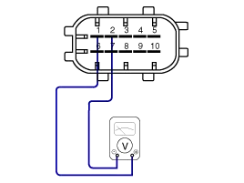
Check the power supply voltage provided to the fuel pressure sensor (FPS).
|
| 4. |
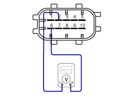
Check the voltage provided to the fuel pressure sensor (FPS) at idle.
|
| 5. |
Check the fuel pressure in the low fuel line.
(Refer to Fuel Delivery System - "Fuel Pressure Test")
|
Circuit Diagram Fuel Pressure Control Module (FPCM) Terminal And Input/Output signal FPCM Terminal Function Pin No.DescriptionConnected to1Fuel pressure sensor (FPS) power supply (+5V)Fuel Pressure Sensor (FPS) 2Fuel Pressure Sensor (FPS) Ground (-)Fuel Pressure Sensor (FPS) 3- 4Fuel pump DC motor (-)Fuel Pump Motor5Fuel pump DC motor (+)Fuel Pump Motor6Fuel pressure sensor (FPS) signal inputFuel pressure sensor (FPS) 7CAN [High]ECM8CAN [Low]ECM9GroundChassis Ground10Battery power (B+)Fuel Pump Relay
Description The fuel pressure sensor (FPS) is installed on the top of the low pressure fuel pump and measures the pressure in the low pressure fuel line.
Other information:
Kia Cadenza YG 2016-2021 Service Manual: Evaporator unit Repair procedures
Inspection 1. Ignition "OFF". 2. Disconnect evaporator temperature sensor. 3. Using the multi-tester, Measure resistance between terminal "1" and "2" of evaporator temperature sensor. Specification Evaporator coretemperature [°C(°F)]Resistance[KΩ]Voltage[V]-20(-4)70.
Kia Cadenza YG 2016-2021 Service Manual: Blower Resistor Repair procedures
Inspection 1. Measure terminal - to - terminal resistance of blower resistor. 2. If measure resistance isnot within specification, the blower resistor must be replaced. Replacement 1. Disconnect the negative (-) battery terminal. 2. Remove the crash pad lower cover (A) and then disconnect the connector (B).
Categories
- Manuals Home
- Kia Cadenza Owners Manual
- Kia Cadenza Service Manual
- Battery Troubleshooting
- General Information
- Timing Chain Repair procedures
- New on site
- Most important about car
