Kia Cadenza YG: IMS (Integrated Memory) / IMS (Integrated Memory System) module Repair procedures
Kia Cadenza YG 2016-2021 Service Manual / Body Electrical System / IMS (Integrated Memory) / IMS (Integrated Memory System) module Repair procedures
| Removal |
| 1. |
Remove the negative (-) battery terminal. |
| 2. |
Remove the driver seat in the car.
(Refer to Body - "Front Seat") |
| 3. |
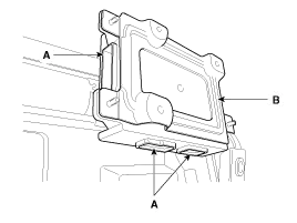
Remove the IMS module (A) after loosening 3 screws in the bottom of seat.
|

| 4. |
Disconnect the IMS module connector (A) and then remove the IMS module (B).
|
| Installation |
| 1. |
Install the IMS module after reconnecting the connector. |
| 2. |
Install the driver seat.
|

Description system outline An optimal seat position set by a driver can be memorized in Power seat unit by IMS SW, which enables restoration of seat position set by the driver despite Playing of this function during drive is banned for safety reasons, and it has emergency stop function of restoration and gearing operation as well Input Specification 1.
Circuit diagram
Other information:
Kia Cadenza YG 2016-2021 Service Manual: Specifications
S
Kia Cadenza YG 2016-2021 Service Manual: Lane Departure Warning System (LDWS) Unit Repair procedures
Removal 1. Disconnect the negative (-) battery terminal. 2. Remove the LDWS unit cover (A). 3. Remove the LDWS unit connector (A). 4. Remove the LDWS unit after widening the mounting clips. Installation 1. Install the LDWS unit. 2.
Categories
- Manuals Home
- Kia Cadenza Owners Manual
- Kia Cadenza Service Manual
- Rail Pressure Sensor (RPS) Schematic Diagrams
- Transaxle Control Module (TCM) Repair procedures
- Body Electrical System
- New on site
- Most important about car

Copyright © 2026 www.kcadenzavg.com - 0.0265