Kia Cadenza YG: Brake System / Rear Disc Brake Repair procedures
Kia Cadenza YG 2016-2021 Service Manual / Brake System / Brake System / Rear Disc Brake Repair procedures
| Removal |
| 1. |
Remove the rear wheel & tire.
|
| 2. |
Release the parking brake. |
| 3. |
Disconnect the EPB actuator connector (A). [EPB Only]
|

| 4. |
Remove the rear shock absorber (B).
(Refer to Suspension System - "Rear shock absorber")
|

| 5. |
Remove the rear upper arm (A). |
| 6. |
Loosen the hose eyebolt (B) and caliper mounting bolts (C), then remove the rear caliper assembly (A).
[Without EPB]
[With EPB]
|


| 7. |
Remove the rear brake disc by loosening the screws (A).
|

| Replacement |
Rear brake pads (Without EPB)
| 1. |
Remove the rear wheel & tire. |
| 2. |
Loosen the guide rod bolt (B) and pivot the caliper (A) up out of the way.
|

| 3. |
Replace pad shim (D), pad retainers (C) and brake pads (B) in the caliper bracket (A).
|

| 4. |
Use a SST (09581-11000) when installing the brake caliper assembly.
|
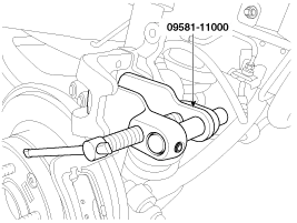
| 5. |
Place the caliper body (A) on the caliper carrier and tighten the guide rod bolts (B).
|
| 6. |
Install the rear wheel & tire.
|
Rear brake pads (With EPB)
| 1. |
Remove the rear wheel & tire. |
| 2. |
Connect the GDS to the data link connector located underneath the dash panel. |
| 3. |
Ignition "ON" & Engine "OFF". |
| 4. |
Release the electric parking brake. |
| 5. |
Select vehicle name and EPB system. |
| 6. |
Select the “PAD change mode”.
|

| 7. |
Select the "C2(Release)".
|

| 8. |
Ignition "OFF". |
| 9. |
Disconnect the electric parking brake actuator connector (A).
|
| 10. |
Loosen the guide rod bolts (B) and then remove caliper body.
|

| 11. |
Replace pad retainers (C) and brake pads (B) in the caliper carrier (A).
|

| 12. |
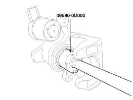
Use a SST (09580-0U000) when installing the brake caliper assembly.
|
| 13. |
Place the caliper body (A) on the caliper carrier and tighten the guide rod bolts (B).
|
| 14. |
Connect the electric parking brake actuator connector (A).
|
| 15. |
Ignition "ON". |
| 16. |
Select the “PAD change mode”.
|
| 17. |
Select the "C1(Apply)".
|

| 18. |
IGN switch “OFF” and remove the GDS. |
| 19. |
Install the rear wheel & tire.
|
| Inspection |
Rear Brake Disc Thickness Check
| 1. |
Check the brake pads for wear and fade. |
| 2. |
Check the brake disc for damage and cracks. |
| 3. |
Remove all rust and contamination from the surface, and
measure the disc thickness at 8 points, at least, of same distance (5mm)
from the brake disc outer circle.
|

| 4. |
If wear exceeds the limit, replace the discs and pad assembly left and right of the vehicle. |
Rear Brake Pad Check
| 1. |
Check the pad wear. Measure the pad thickness and replace it, if it is less than the specified value.
|
| 2. |
Check that grease is applied, to sliding contact points and the pad and backing metal for damage.
|

Rear Brake Disc Runout Check
| 1. |
Place a dial gauge about 5mm (0.2 in.) from the outer circumference of the brake disc, and measure the runout of the disc.
|

| 2. |
If the runout of the brake disc exceeds the limit specification, replace the disc, and then measure the runout again. |
| 3. |
If the runout exceeds the limit specification, install the
brake disc after turning it 180° and then check the runout of the brake
disc again. |
| 4. |
If the runout cannot be corrected by changing the position of the brake disc, replace the brake disc. |
| Installation |
| 1. |
Installation is the reverse of removal. |
| 2. |
Use a SST (09581-11000, 09580-0U000) when installing the brake caliper assembly.
[Without EPB]
[With EPB]
|

| 3. |
After installation, bleed the brake system.
(Refer to Brake system bleeding) |
Components (Without EPB) 1. Guide rod bolt2. Bleed screw3. Caliper carrier4. Caliper body5. Inner pad shim6. Brake pad7. Pad retainer Components (With EPB) 1.
Other information:
Kia Cadenza YG 2016-2021 Service Manual: Components and Components Location
C
Kia Cadenza YG 2016-2021 Service Manual: Compressor Oil Repair procedures
Oil Specification 1. The HFC-134a system requires synthetic (PAG) compressor oil whereas the R-12 system requires mineral compressor oil. The two oils must never be mixed. 2. Compressor (PAG) oil varies according to compressor model. Be sure to use oil specified for the model of compressor.
Categories
- Manuals Home
- Kia Cadenza Owners Manual
- Kia Cadenza Service Manual
- General Information
- Body Electrical System
- Alternator Schematic Diagrams
- New on site
- Most important about car

Copyright © 2026 www.kcadenzavg.com - 0.0214