Kia Cadenza YG: Multifunction switch / Repair procedures
Kia Cadenza YG 2016-2021 Service Manual / Body Electrical System / Multifunction switch / Repair procedures
| Inspection |
Lighting Switch Inspection
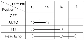
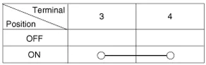
With the multi function switch in each position, make sure
that continuity exists between the terminals below. If continuity is not
as specified, replace the multi-function switch.
Lighting Switch (Auto Light)
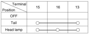
Lighting Switch
Dimmer And Passing Switch

HU : Head lamp high beam
HL : Head lamp low beam
P : Head lamp passing switch
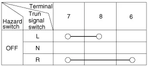
Turn Signal Switch
Front Fog Lamp Switch
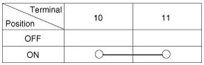
Front & Rear Fog Lamp Switch

Wiper And Washer Switch Inspection
With the multi function switch in each position, make sure
that continuity exists between the terminals below. If continuity is not
as specified, replace the multi-function switch.

Wiper Switch

Washer Switch
| Inspection (With GDS) |
| 1. |
Check BCM input/output specification of multifunction switch
using the GDS. If the specification is abnormal, replace the lamp or
wiper switch. |
| 2. |
If diagnosis is required on the multifunction switch, select model and "IPM". |
| 3. |
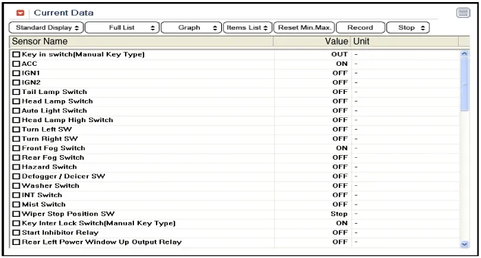
To consult the present input/output value of BCM, "Current
DATA". It provides information of BCM input/output conditions of power
supply, turn signal/brake lamp, headlamp, door, locks, outside mirror,
wiper, auto-light and transmitters etc.
|
| 4. |
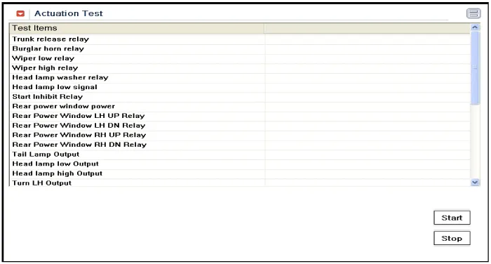
To perform compulsory operation on BCM input factors, select "ACTUATION TEST".
|
| Removal |
| 1. |
Remove the steering column upper and lower shrouds after removing 3 screws.
|

| 2. |
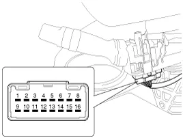
Disconnect the lighting switch connector (A) and wiper & washer switch connector (B).
|


| 3. |
If necessary of removing the wiper & washer switch (A),
release the lock of wiper switch using tool without removing the
steering wheel and the clock spring.
|


| 4. |
Remove the steering wheel.
(Refer to Steering System - "Steering Column & Shaft") |
| 5. |
Remove the clock spring.
(Refer to Restraint - "Airbag Module") |
| 6. |
Remove the multifunction switch assembly (A) after loosening the mounting screws (2EA).
|

| Installation |
| 1. |
Install the multifunction switch. |
| 2. |
Install the clock spring and steering. |
| 3. |
Install the steering column upper and lower shrouds. |
| 4. |
Install the steering wheel.
|
Component (1) 1. Steering column2. Lighting switch3. Wiper switch4. Screw5. Steering angle sensor6. Clock spring Component (2)
Other information:
Kia Cadenza YG 2016-2021 Service Manual: Repair procedures
Removal 1. Remove the trunk trim in the trunk after removing the screws and clips. (Refer to Body - "Trunk") 2. Remove the camera holder (A) as shown arrow direction, and then remove the back view camera (B). Installation 1. Install the back view camera and camera holder.
Kia Cadenza YG 2016-2021 Service Manual: Repair procedures
Refrigerant System Service Basics Refrigerant Recovery Use only service equipment that is U.L-listed and is certified to meet the requirements of SAE J2210 to remove HFC-134a(R-134a) from the air conditioning system. – Air conditioning refrigerant or lubricant vapor can irritate your eyes, nose, or th
Categories
- Manuals Home
- Kia Cadenza Owners Manual
- Kia Cadenza Service Manual
- Components and Components Location
- Brake System
- Rail Pressure Sensor (RPS) Schematic Diagrams
- New on site
- Most important about car

Copyright © 2026 www.kcadenzavg.com - 0.0257