Kia Cadenza YG: ESC(Electronic Stability Control) System / Schematic Diagrams
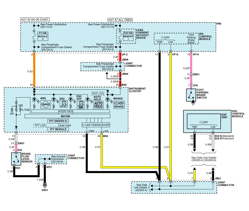
| Circuit Diagram - ESC (1) |
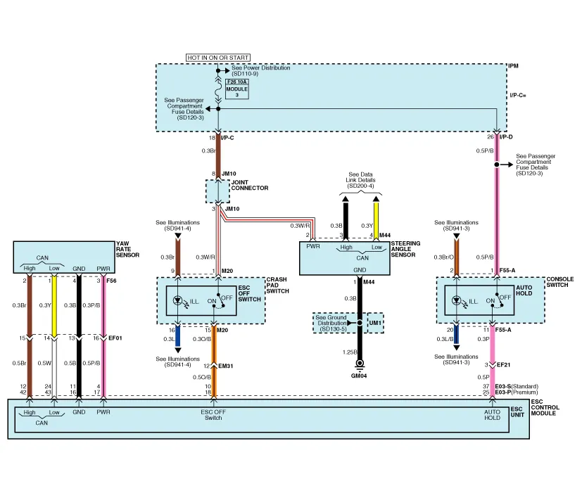
| Circuit Diagram - ESC (2) |
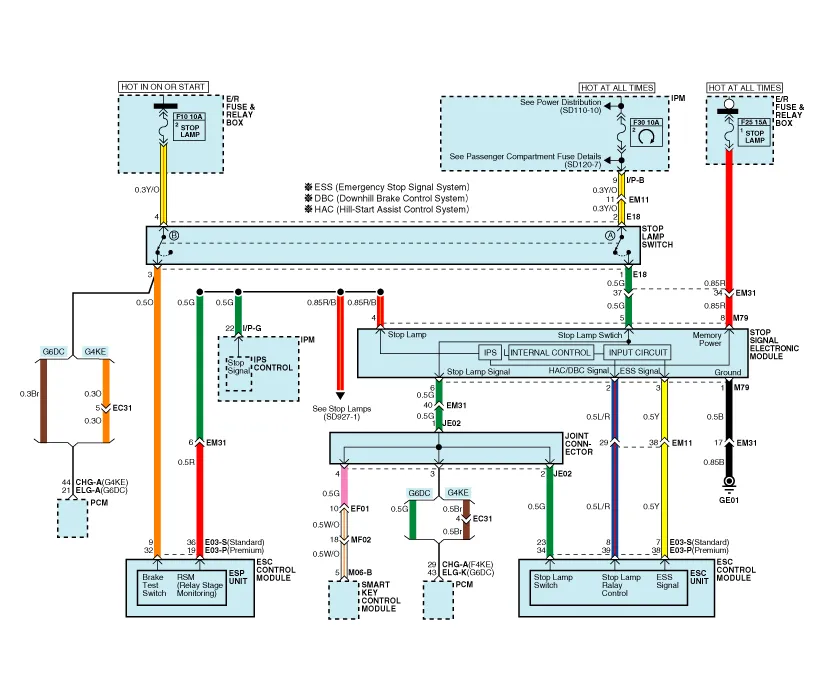
| Circuit Diagram - ESC (3) |
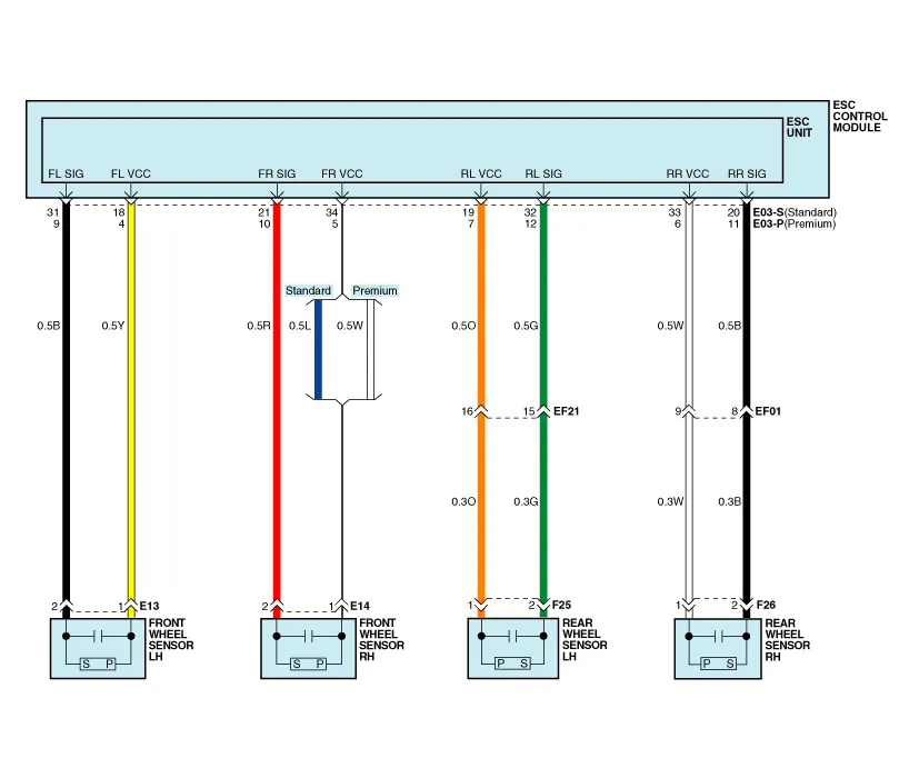
| Circuit Diagram - ESC (4) |
| Circuit Diagram - ESC (5) |
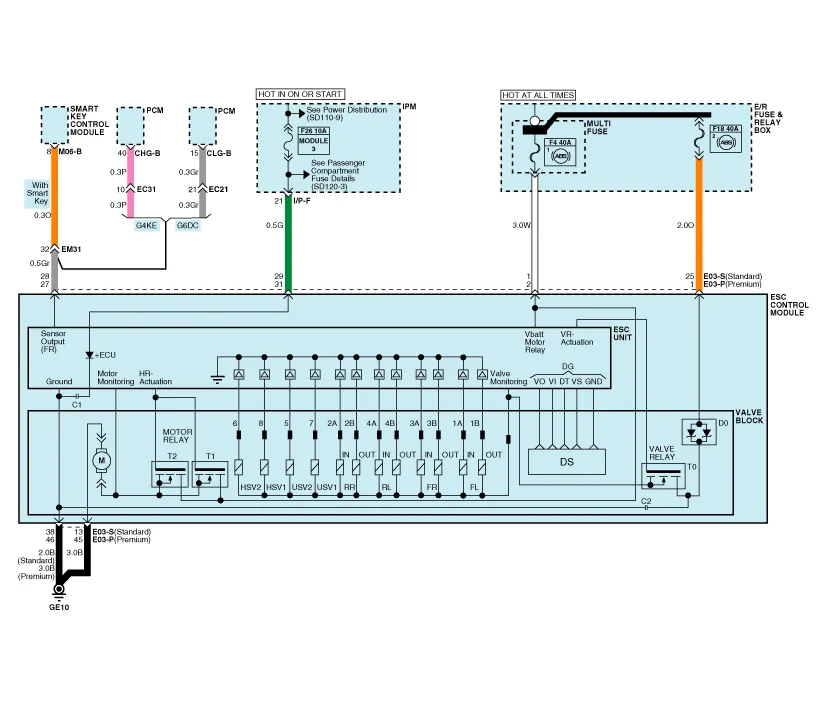
| ESC connector input/output |

| Connector Terminal | Specification | ||
| Pin No | Description | ||
| Standard | Premium | ||
| 29 | 31 | IGNITION1(+) | High level of wake up voltage : 4.5V < V < 16.0V Low level of wake up voltage : V < 2.4V Max. current : I < 50mA |
| 25 | 1 | POS. BATTERY 1.(SOLENOID) | Over voltage range : 17.0 ± 0.5V Operating voltage range : 10.0 ± 0.5V < V < 16.0 ± 0.5V Low voltage range : 7.0 ± 0.5V < V < 9.5 ± 0.5V Max. current : I < 40A Max. leakage current : I < 0.25mA |
| 1 | 2 | POS. BATTERY 2.(MOTOR) | Operating voltage range: 10.0 ± 0.5V < V < 16.0 ± 0.5V Rush current : I < 110A Max current : I < 40A Max leakage current : I < 0.25mA |
| 38 | 46 | GROUND | Rated current : I <550mA Max. current: I < 40A |
| 13 | 45 | PUMP MOTOR GROUND | Rush current : I < 110A Max current : I < 40A |
| 11 | 16 | SENSOR GROUND | Rated current : I <250mA |
| 4 | 17 | SENSOR POWER | Max current Capability : I < 250mA Max voltage : V_BAT1 -0.8V |
| 23 | 34 | BRAKE LIGHT SWITCH | Input voltage (Low) : V < 2V Input voltage (High) : V > 6V Max. Input current : I < 3mA (@12.8V) |
| 10 | 18 | ESC ON/OFF SWITCH | |
| 28 | 27 | SENSOR FRONT RIGHT OUTPUT | External pull up resistance : 1 KΩ < R Output duty :50 ± 20% |
| 14 | 15 | CAN BUS LINE(LOW) | Max. Input current : I < 10mA |
| 26 | 14 | CAN BUS LINE(HIGH) | |
| 18 | 4 | SENSOR FRONT LEFT POWER | Output voltage : V_BAT1 -0.6V ~ V_BAT1 -1.1V Output current : Max 30mA |
| 34 | 5 | SENSOR FRONT RIGHT POWER | |
| 19 | 7 | SENSOR REAR LEFT POWER | |
| 33 | 6 | SENSOR REAR RIGHT POWER | |
| 31 | 9 | SENSOR FRONT LEFT SIGNAL | Input current LOW : 5.9 ~ 8.4mA Input current HIGH : 11.8 ~ 16.8mA Frequency range : 1 ~ 2500Hz Input duty : 50 ± 10% |
| 21 | 10 | SENSOR FRONT RIGHT SIGNAL | |
| 32 | 12 | SENSOR REAR LEFT SIGNAL | |
| 20 | 11 | SENSOR REAR RIGHT SIGNAL | |
| 12 | 42 | CAN SENSOR LINE (HIGH) | Max. input current : I < 10mA |
| 24 | 43 | CAN SENSOR LINE (LOW) | |
| 8 | 39 | HAC BRAKE RELAY DRIVE | Max. Current : I< 180mA Max.Output Low Voltage : V< 1.2V |
| 7 | 38 | ESS RELAY DRIVE | |
| 9 | 32 | BRAKE SWITCH | Input voltage (Low) : V < 2V Input voltage (High) : V > 6V Max. Input current : I < 10mA |
| 36 | 19 | RELAY STATE MONITORING | |
Description of ESC Electronic Stability Control (ESC) recognizes critical driving conditions, such as panic reactions in dangerous situations, and stabilizes the vehicle by wheel-individual braking and engine control intervention.
Failure Diagnosis 1. In principle, ESC and TCS controls are prohibited in case of ABS failure. 2. When ESC or TCS fails, only the failed system control is prohibited.
Other information:
Kia Cadenza YG 2016-2021 Service Manual: Surround View Monitoring Switch Repair procedures
Removal 1. Disconnect the negative (-) battery terminal. 2. Remove the floor console upper cover. (Refer to Body - "Floor Console Assembly") 3. Disconnect the console upper cover connector (A). 4. Remove the cup holder assembly (A) after loosening the mounting screws.
Kia Cadenza YG 2016-2021 Service Manual: Specifications
Specification Air Conditioner ItemSpecificationCompressorType6VSX16Oil type & CapacityPAG OIL 100±10Pulley type6PK-TYPEDisplacement160cc/revCondenserHeat rejection14,400 ±5% kcal/hrA/C Pressure transducerThe method to measure the pressureVoltage= 0.
Categories
- Manuals Home
- Kia Cadenza Owners Manual
- Kia Cadenza Service Manual
- Steering System
- Automatic Transaxle System
- Body (Interior and Exterior)
- New on site
- Most important about car
