Kia Cadenza YG: Button Engine Start System / Schematic Diagrams
| Circuit Diagram (1) |
| Circuit Diagram (2) |
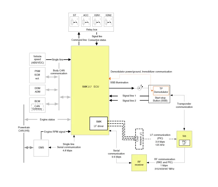
Component Location 1. Start Stop Button(SSB)2. FOB key3. RF receiver4. Smart key unit5. Interior antenna 16. Interior antenna 2 7.
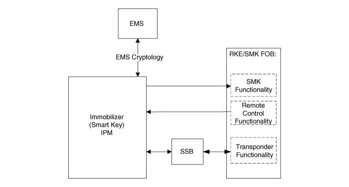
Description System Overview The System offers the following features: – Human / machine interface through a 1-stage button, for terminal switching and engine start.
Other information:
Kia Cadenza YG 2016-2021 Service Manual: Blind Spot Detection Variant Coding Description and Operation
Description The used radar frequency of BSD is two, "North America region" and "Except North America region". If it replaces BSD unit, BSD unit has to perform the procedure of variant coding. BSD Variant Coding 1. Select the "BSD Variant Coding" procedure in BSD system.
Kia Cadenza YG 2016-2021 Service Manual: Power Mosfet Repair procedures
Inspection 1. Ignition "ON" 2. Manually operate the control switch and measure the voltage of blower motor. 3. Select the control switch to raise voltage until high speed. Specification FanMotor VoltageManualFirst speed3.8 ±0.5VSecond speed5.
Categories
- Manuals Home
- Kia Cadenza Owners Manual
- Kia Cadenza Service Manual
- Restraint
- Rail Pressure Sensor (RPS) Schematic Diagrams
- Body Electrical System
- New on site
- Most important about car
