Kia Cadenza YG: Seat Electrical / Seat Heater Switch Repair procedures
Kia Cadenza YG 2016-2021 Service Manual / Body Electrical System / Seat Electrical / Seat Heater Switch Repair procedures
| Inspection |
Front Seat Heater Switch
| 1. |
Disconnect the negative (-) battery terminal. |
| 2. |
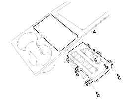
Remove the floor console upper cover (A).
(Refer to Body - "Console") |
| 3. |
Remove the seat heater switch connector (A) from the floor console upper cover.
|
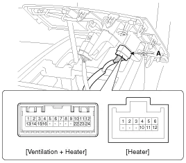
| 4. |
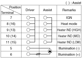
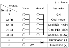
Operate each seat heater switch and check that continuity exists between the terminals.
If there is no continuity, replace the seat heater switch
[Ventilation + Heater]
[Ventilation + Heater]
[Heater]
|
Rear Seat Heater Switch
| 1. |
Disconnect the negative (-) battery terminal. |
| 2. |
Open the rear seat arm rest (A).
|
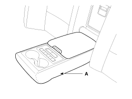
| 3. |
Remove the rear seat arm rest upper cover (A).
|
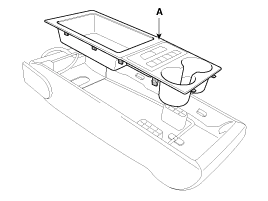
| 4. |
Disconnect the connector (A).
|

| 5. |
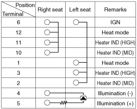
Turn rear seat heater switch ON and check that continuity exists between the terminals.
|
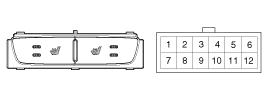
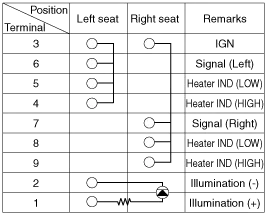
| 6. |
If there is no continuity, replace the seat heater switch (A).
|
Circuit Diagram
Components (1) 1. Ventilation blower2. Ventilation ECU3. Ventilation seat switch Components (2)
Other information:
Kia Cadenza YG 2016-2021 Service Manual: Repair procedures
Teaching Procedures 1. Key Teaching Procedure Key teaching must be done after replacing a defective PCM(ECM) or when providing additional keys to the vehicle owner. The procedure starts with an PCM(ECM) request for vehicle specific data (PIN code: 6digits) from the tester.
Kia Cadenza YG 2016-2021 Service Manual: Auto defoging actuator Repair procedures
Inspection 1. Ignition "OFF”. 2. Disconnect the connector of auto defog control actuator. 3. Verify that the auto defog control actuator operates to the defrost ON mode when connecting 12V to the terminal 3 and grounding terminal 7. 4.
Categories
- Manuals Home
- Kia Cadenza Owners Manual
- Kia Cadenza Service Manual
- Engine Mechanical System
- Body Electrical System
- Restraint
- New on site
- Most important about car

Copyright © 2026 www.kcadenzavg.com - 0.0175