Kia Cadenza YG: Engine Mechanical System / Special Service Tools
Kia Cadenza YG 2016-2021 Service Manual / Engine Mechanical System / Special Service Tools
| Special Service Tools |
| Tool (Number and name) | Illustration | Use |
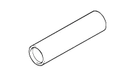
| Crankshaft front oil seal installer (09231-3C100) |
| Installation of the front oil seal |
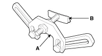
| Ring gear stopper (09231-2B100) |
| Removal and installation of crankshaft pulley bolt |
| Ring gear stopper A : (09231-3D100) B : (09231-2W100) |
| Removal and installation of crankshaft pulley bolt. |
| Torque angle adapter (09221-4A000) |
| Installation of bolts & nuts needing an angular method |
| Valve stem seal remover (09222-29000) |
| Removal of the valve stem seal |
| Valve stem seal installer (09222-2W100) |
| Installation of the valve stem seal |
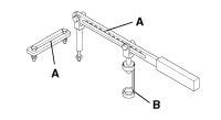
| Valve spring compressor & holder (09222-3K000) (09222-3K100) |
| Removal and installation of the intake or exhaust valves A : 09222-3K000 B : 09222-3K100 (holder) |
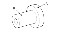
| Crankshaft rear oil seal installer (09231-3C200) (09231-H1100) |
| Installation of the crankshaft rear oil seal A : 09231-3C200 B : 09231-H1100 |
| Oil pan remover (09215-3C000) |
| Removal of oil pan |


Specifications DescriptionSpecificationsLimitGeneralTypeV-type, DOHCNumber of cylinders6Bore92mm(3.6220in.)Stroke83.8mm(3.2992in.)Total displacement3,342cc(203.
Compression Pressure Inspection If the there is lack of power, excessive oil consumption or poor fuel economy, measure the compression pressure.
Other information:
Kia Cadenza YG 2016-2021 Service Manual: Blind Spot Detection Unit Repair procedures
Removal 1. Disconnect the negative (-) battery terminal. 2. Remove the rear bumper. (Refer to Body - "Rear Bumper") 3. Remove the BSD unit (A) after loosening the mounting screws. Take care not to separate the bracket from rear bumper when removing the BSD sensor.
Kia Cadenza YG 2016-2021 Service Manual: Special Service Tools
S
Categories
- Manuals Home
- Kia Cadenza Owners Manual
- Kia Cadenza Service Manual
- Body (Interior and Exterior)
- Brake System
- Body Electrical System
- New on site
- Most important about car

Copyright © 2026 www.kcadenzavg.com - 0.0296