Kia Cadenza YG: Automatic Transaxle Control System / SS-A Solenoid Valve(ON/OFF) Repair procedures
Kia Cadenza YG 2016-2021 Service Manual / Automatic Transaxle System / Automatic Transaxle Control System / SS-A Solenoid Valve(ON/OFF) Repair procedures
| Inspection |
| 1. |
Turn ignition switch OFF. |
| 2. |
Remove the battery and battery tray.
(Refer to Engine Electrical System - "Battery") |
| 3. |
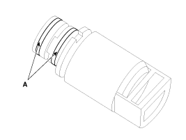
Disconnect the solenoid valve connector (A).
|
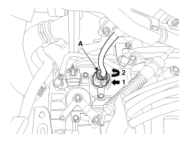
| 4. |
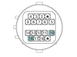
Measure the resistance between power terminal (10) and signal terminal (18).
|
| Removal |
| 1. |
Remove the under cover.
(Refer to Engine Mechanical System - "Engine Room Under Cover") |
| 2. |
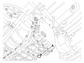
Remove the ATF drain plug (A), allow the fluid to drain out and then reinstall the drain plug.
|

| 3. |
Remove the battery and battery tray.
(Refer to Engine Electrical System - "Battery") |
| 4. |
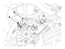
Remove the wiring bracket (A) and the air breather hose (B).
|
| 5. |
Lift the vehicle after loosening valve body cover upper bolts. |
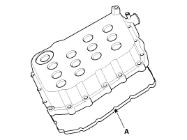
| 6. |
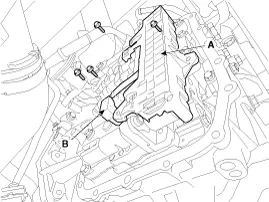
Remove the valve body cover (A) by loosening bolts.
|

| 7. |
Remove the solenoid valve harness (A) and oil temperature sensor (B) after removing the bolts.
|
| 8. |
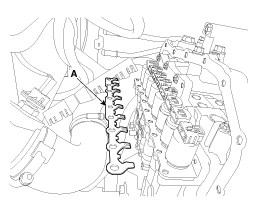
Remove solenoid valve support bracket (A).
|
| 9. |
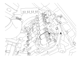
Remove the SS-A solenoid valve (A).
|
| Installation |
| 1. |
Install in the reverse order of removal. |
|
Circuit Diagram
Specification ItemSpecificationControl typeON/OFFCurrent value (mA)5.0 Coil resistance(Ω)10 ~ 11
Other information:
Kia Cadenza YG 2016-2021 Service Manual: Adaptive Front Lighting System Description and Operation
Description AFLS Unit(ECU) AFLS located in Cockpit Module is provided information of vehicle (steering wheel signal,vehicle speed, inclination of vehicle). Based on provided information , it calculates algorithm and adjust Low beam of H/Lamp. It transmits driving information by using LIN protocol, it is operated in Fail-safe reaction mode
Kia Cadenza YG 2016-2021 Service Manual: Repair procedures
Diagnosis With GDS 1. BSD system defects can be quickly diagnosed with the GDS. GDS operates actuator quickly to monitor, input/output value and self diagnosis. 2. Connect the cable of GDS to the data link connector in driver side crash pad lower panel, turn the power on GDS.
Categories
- Manuals Home
- Kia Cadenza Owners Manual
- Kia Cadenza Service Manual
- General Information
- Body Electrical System
- Schematic Diagrams
- New on site
- Most important about car

Copyright © 2026 www.kcadenzavg.com - 0.0273