Kia Cadenza YG: Starting System / Starter Relay Repair procedures
| Inspection |
| 1. |
Disconnect the battery negative terminal. |
| 2. |
Remove the fuse box cover. |
| 3. |
Remove the starter relay (A).
|

| 4. |
Check for continuity between the terminals (30 and 87) using an ohmmeter.
| ||||||||||
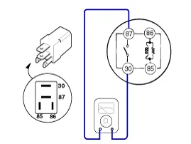
| 5. |
Apply 12V to the terminal 85 and ground to the terminal 86 and then check for continuity between the terminals (30 and 87).
| ||||||||||

| 6. |
Install the starter relay. |
| 7. |
Install the fuse box cover. |
Removal 1. Turn the ignition switch OFF and disconnect the battery negative (-) cable. 2. Remove the under (A) and (B). 3. Remove the starter cover (A).
Other information:
Kia Cadenza YG 2016-2021 Service Manual: Description and Operation
Description Surround View Monitoring System (SVM) is the system that allows video monitoring of 360 degrees around the vehicle. The system includes 4 ultra optical camera mounted around the vehicle (front, both sides, rear). The video from these cameras are applied with distortion compensation, time point conversion, and video merging
Kia Cadenza YG 2016-2021 Service Manual: Specifications
Specification ItemSpecificationUltrasonic sensorVoltage ratingDC 12 VDetecting range30 cm ~ 120 cmOperation voltageDC 9 ~ 16 VOperation currentMAX 300 mAOperation temperature-30°C ~ +80°C (-22°C ~ +176°C)Operation frequency48 ± 5 KHzEffective operating velocity10 KPH (6.
Categories
- Manuals Home
- Kia Cadenza Owners Manual
- Kia Cadenza Service Manual
- Restraint
- Components and Components Location
- Emission Control System
- New on site
- Most important about car
