Kia Cadenza YG: Timing System / Timing Chain Components and Components Location
| Components |
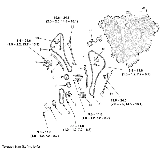
| 1. Oil pump chain cover 2. Oil pump sprocket 3. Oil pump chain 4. Oil pump tensioner assembly 5. Crankshaft oil pump sprocket 6. Crankshaft RH chain sprocket | 7. RH Timing chain auto tensioner 8. RH Timing chain tensioner arm 9. RH Timing chain 10. RH Timing chain cam to cam guide 11. RH Timing chain guide 12. LH Timing chain auto tensioner | 13. LH Timing chain tensioner arm 14. Crankshaft LH chain sprocket 15. LH Timing chain 16. LH Timing chain cam to cam guide 17. LH Timing chain guide 18. Tensioner adapter |
Removal 1. Remove the LH/RH cylinder head cover. (Refer to Cylinder Head Assembly - "Cylinder Head Cover") 2. Remove the lower oil pan. (Refer to Lubrication System - "Oil Pan") 3.
Removal 1. Set No.1 cylinder to TDC/compression. (1) Turn the crankshaft pulley clockwise and align its groove with the timing mark "T" of the lower timing chain cover.
Other information:
Kia Cadenza YG 2016-2021 Service Manual: Lane Departure Warning System (LDWS) Unit Repair procedures
Removal 1. Disconnect the negative (-) battery terminal. 2. Remove the LDWS unit cover (A). 3. Remove the LDWS unit connector (A). 4. Remove the LDWS unit after widening the mounting clips. Installation 1. Install the LDWS unit. 2.
Kia Cadenza YG 2016-2021 Service Manual: Troubleshooting
Troubleshooting Problem Symptoms Table Before replacing or repairing air conditioning components, first determine if the malfunction is due to the refrigerant charge, air flow or compressor. Use the table below to help you find the cause of the problem.
Categories
- Manuals Home
- Kia Cadenza Owners Manual
- Kia Cadenza Service Manual
- Body (Interior and Exterior)
- Transaxle Control Module (TCM) Repair procedures
- Rail Pressure Sensor (RPS) Schematic Diagrams
- New on site
- Most important about car
