
Kia Cadenza YG: Brake System / Master Cylinder Components and Components Location
| Components |
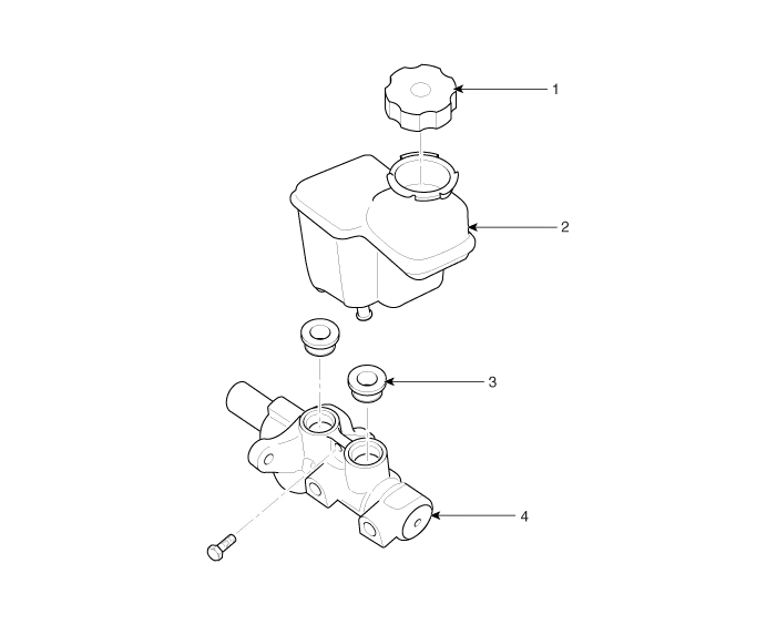
| 1. Reservoir cap 2. Reservoir | 3. Grommet 4. Master cylinder |
Brake Booster Operating Test For simple checking of the brake booster operation, carry out the following tests. 1. Run the engine for one or two minutes, and then stop it.
Removal 1. Turm ignition switch OFF and disconnect the negative (-) battery cable. 2. Remove the air duct (B) and air cleaner assembly (A). 3.
Other information:
Kia Cadenza YG 2016-2021 Service Manual: Photo Sensor Description and Operation
Description 1. The photo sensor is located at the center of defrost nozzle. 2. The photo sensor contains a photovoltaic (sensitive to sunlight) diode. The solar radiation received by its light receiving portion, generates an electromotive force in proportion to the amount of radiation received which is transferred to the automatic tem
Kia Cadenza YG 2016-2021 Service Manual: Power Mosfet Repair procedures
Inspection 1. Ignition "ON" 2. Manually operate the control switch and measure the voltage of blower motor. 3. Select the control switch to raise voltage until high speed. Specification FanMotor VoltageManualFirst speed3.8 ±0.5VSecond speed5.
Categories
- Manuals Home
- Kia Cadenza Owners Manual
- Kia Cadenza Service Manual
- General Information
- Suspension System
- Engine Electrical System
- New on site
- Most important about car
