Kia Cadenza YG: Engine Control System / Rail Pressure Sensor (RPS) Schematic Diagrams
Kia Cadenza YG 2016-2021 Service Manual / Engine Control / Fuel System / Engine Control System / Rail Pressure Sensor (RPS) Schematic Diagrams
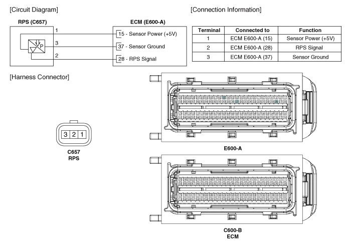
| Circuit Diagram |
Signal Waveform
Inspection 1. Connect the GDS on the Data Link Connector (DLC). 2. Measure the output voltage of the RPS at idle and various engine speed. ConditionOutput Voltage (V)Idle Approx.
Other information:
Kia Cadenza YG 2016-2021 Service Manual: Auto Head lamp leveling Unit Repair procedures
Removal Height Sensor 1. Remove the height sensor connector (A). 2. Loosen the mounting bolts(Body: 2EA, chassis: 1EA) from height sensor bracket. Tightening torque : 3 ~ 5N.m (30 ~ 50kgf.m, 2.21 ~ 3.68lb-ft) 3. Remove the height sensor.
Kia Cadenza YG 2016-2021 Service Manual: Condenser Repair procedures
Inspection 1. Check the condenser fins for clogging and damage. If clogged, clean them with water, and blow them with compressed air. If bent, gently bend them using a screwdriver or pliers. 2. Check the condenser connections for leakage, and repair or replace it, if required.
Categories
- Manuals Home
- Kia Cadenza Owners Manual
- Kia Cadenza Service Manual
- Steering System
- Engine Control / Fuel System
- Body Electrical System
- New on site
- Most important about car

Copyright © 2026 www.kcadenzavg.com - 0.0248