Kia Cadenza YG: Surround View Monitoring (SVM) System / Repair procedures
Kia Cadenza YG 2016-2021 Service Manual / Body Electrical System / Surround View Monitoring (SVM) System / Repair procedures
| Inspection |
Tolerance Calibration
Tolerance calibration compensates for the error margins of
surround view video that occur due to the installation tolerance when
the four cameras that comprise the SVM system are installed.
You must carry out tolerance calibration if you do any of the following.
| – |
Remove and install a wide camera. |
| – |
Conduct a body task that causes the focus of the wide camera to change, such as a trunk task. |
| – |
Replace the door mirror that has a wide camera. |
| – |
Replace the surround view monitoring unit. |
Environment that is required to perform compensation task
Tolerance Calibration Procedures
| 1. |
It shall be prepared as follows.
Apply foot brake or electronic parking brake (EPB) for the vehicle not to move. |
| 2. |
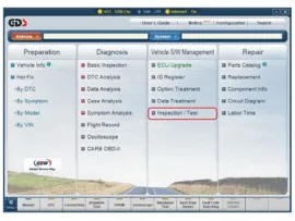
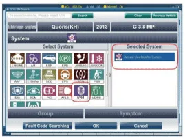
The following procedure shall be performed to check the
normal operation of SVM ECU and camera before entering into the
tolerance calibration mode.
|
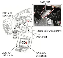
| 3. |
The equipment and vehicle shall be connected as shown in the
following figure in order to perform the SVM manual screen image
calibration.
|
| 4. |
Off the ignition power of the vehicle. |
| 5. |
Remove the glove box to couple the connector of the GDS-SVM with SVM unit.
(Refer to Body Electrical System - "Surround View Monitoring Unit") |
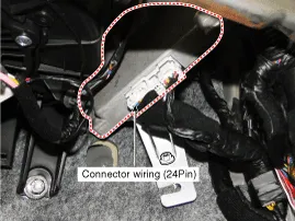
| 6. |
Disconnect the connector (24 pin) coupled from SVM unit to wiring harness on the vehicle.
|
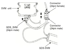
| 7. |
Connect the connector (24 pin) of the GDS-SVM image capture equipment to the point of SVM unit connector.
It is connected in T shape as shown in the following figure.
|

| 8. |
Connect the GDS VCI and vehicle with DLC cable.
|
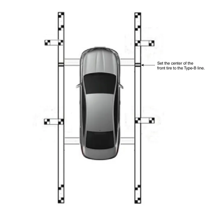
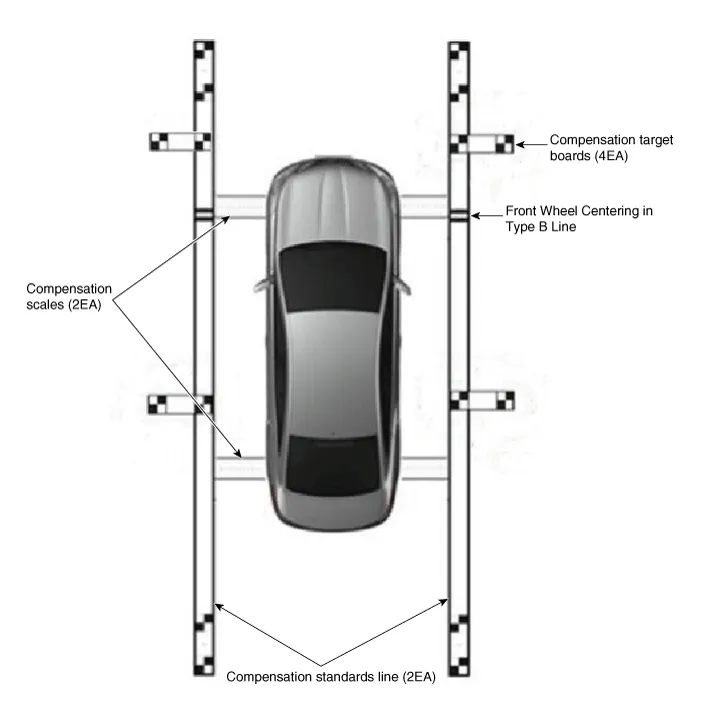
| 9. |
Install the calibration scale (2EA), calibration standard
line board (2EA) and calibration target board (4EA) near to the vehicle
by referring to the enclosed instruction manual.
|
| 10. |
Keep the ignition in ON position at the state of vehicle stop
and check the ''P'' position of gear lever and lock the parking brake
even on the flat ground. |
| 11. |
Perform the work with the SVM switch in the vehicle set to ‘ON.’ |
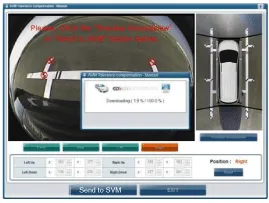
| 12. |
Perform SVM manual tolerance compensation according to GDS diagnostics display.
|
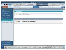
| 13. |
The next procedure is to proceed by referring to the GDS
screen instructions and the ‘manual tolerance compensation’ manual
supplied along with the equipment.
|
Circuit Diagram SVM System Input/Output 1. Camera input ItemSpecificationLens angle of view190 degreesAngle of viewHorizontal186 degreesVertical135 degreesFunctionProvides the original image of the wide angle image (no additional function)Application locationSame camera applied to the front, rear, left and right 2.
Other information:
Kia Cadenza YG 2016-2021 Service Manual: Components and Components Location
C
Kia Cadenza YG 2016-2021 Service Manual: Compressor Oil Repair procedures
Oil Specification 1. The HFC-134a system requires synthetic (PAG) compressor oil whereas the R-12 system requires mineral compressor oil. The two oils must never be mixed. 2. Compressor (PAG) oil varies according to compressor model. Be sure to use oil specified for the model of compressor.
Categories
- Manuals Home
- Kia Cadenza Owners Manual
- Kia Cadenza Service Manual
- Schematic Diagrams
- Alternator Schematic Diagrams
- Timing Chain Repair procedures
- New on site
- Most important about car

Copyright © 2026 www.kcadenzavg.com - 0.0177