Kia Cadenza YG: Automatic Transaxle Control System / 35R Clutch Control Solenoid Valve(35R/C_VFS) Repair procedures
| Inspection |
| 1. |
Turn ignition switch OFF. |
| 2. |
Remove the battery and battery tray.
(Refer to Engine Electrical System - "Battery") |
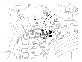
| 3. |
Disconnect the solenoid valve connector (A).
|
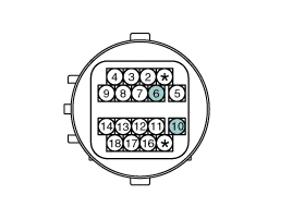
| 4. |
Measure the resistance between power terminal (10) and signal terminal (6).
|
| Replacement |
If a solenoid valve of VFS type needs to be replaced, the
valve body assembly should be replaced and the oil pressure should be
adjusted. If the solenoid valve is replaced individually, it is not
possible to adjust the oil pressure without additional equipment, and if
the oil pressure adjustment procedure is not performed, a shift shock
or delay may occur. |

| 1. |
Replace the valve body assembly.
(Refer to Hydraulic System - "Valve Body") |
Circuit Diagram
Specification Item SpecificationControl typeN/L (Normal Low)Control pressure kpa(kgf/cm², psi)"9.81 ~ 500.14(0.1 ~ 5.1, 1.42 ~ 72.54)"Current value (mA)50 ~ 850Coil resistance(Ω)5.
Other information:
Kia Cadenza YG 2016-2021 Service Manual: Adaptive Front Lighting System Description and Operation
Description AFLS Unit(ECU) AFLS located in Cockpit Module is provided information of vehicle (steering wheel signal,vehicle speed, inclination of vehicle). Based on provided information , it calculates algorithm and adjust Low beam of H/Lamp. It transmits driving information by using LIN protocol, it is operated in Fail-safe reaction mode
Kia Cadenza YG 2016-2021 Service Manual: Heater Unit Components and Components Location
Component Location Components 1. Heater Case (LH)2. Separator3. Evaporator Core4. Shower Duct (LH)5. Heater Core Cover6. Heater Core7. Mode Actuator8. Mode Cam9. Temp Actuator (Drive)10. Vent Door Arm11. Floor Door Arm 1. Heater Case (RH)2.
Categories
- Manuals Home
- Kia Cadenza Owners Manual
- Kia Cadenza Service Manual
- Fuel Delivery System
- Engine Control / Fuel System
- Transaxle Control Module (TCM) Repair procedures
- New on site
- Most important about car
