Kia Cadenza YG: Engine Control System / Accelerator Position Sensor (APS) Repair procedures
Kia Cadenza YG 2016-2021 Service Manual / Engine Control / Fuel System / Engine Control System / Accelerator Position Sensor (APS) Repair procedures
| Inspection |
| 1. |
Connect the GDS on the Data Link Connector (DLC). |
| 2. |
Turn the ignition switch ON. |
| 3. |
Measure the output voltage of the APS 1 and 2 at C.T and W.O.T.
|
| Removal |
| 1. |
Turn the ignition switch OFF and disconnect the negative (-) battery cable. |
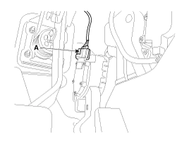
| 2. |
Disconnect the accelerator position sensor connector (A).
|
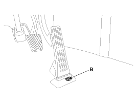
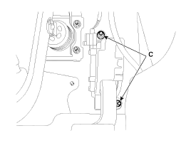
| 3. |
Remove the installation bolt (B) and nuts (C), and the remove the accelerator pedal medule.
|
| Installation |
| 1. |
Install in the reverse order of removal.
|
Circuit Diagram
Description Fuel Tank Pressure Sensor (FTPS) is a component of the evaporative emission control system and is installed on the fuel tank, the fuel pump, or the canister.
Other information:
Kia Cadenza YG 2016-2021 Service Manual: Blind Spot Detection Switch Repair procedures
Removal 1. Disconnect the negative (-) battery terminal. 2. Remove the passenger compartment junction box cover. 3. Remove the driver side cover (A). 4. Remove the crash pad side switch assembly (A) by pushing it through side cover hole.
Kia Cadenza YG 2016-2021 Service Manual: Special Service Tools
S
Categories
- Manuals Home
- Kia Cadenza Owners Manual
- Kia Cadenza Service Manual
- Alternator Schematic Diagrams
- Specifications
- General Information
- New on site
- Most important about car

Copyright © 2026 www.kcadenzavg.com - 0.0197