Kia Cadenza YG: Engine Control System / Accelerator Position Sensor (APS) Schematic Diagrams
| Circuit Diagram |
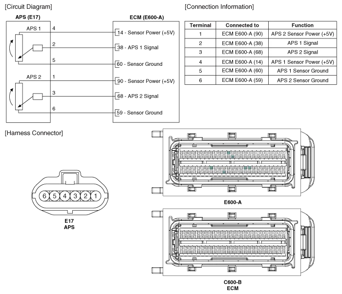
Specification AcceleratorPositionOutput Voltage (V)APS1APS2C.T0.7 ~ 0.80.29 ~ 0.46W.O.T3.85 ~ 4.351.93 ~ 2.18
Inspection 1. Connect the GDS on the Data Link Connector (DLC). 2. Turn the ignition switch ON. 3. Measure the output voltage of the APS 1 and 2 at C.
Other information:
Kia Cadenza YG 2016-2021 Service Manual: Blower Resistor Repair procedures
Inspection 1. Measure terminal - to - terminal resistance of blower resistor. 2. If measure resistance isnot within specification, the blower resistor must be replaced. Replacement 1. Disconnect the negative (-) battery terminal. 2. Remove the crash pad lower cover (A) and then disconnect the connector (B).
Kia Cadenza YG 2016-2021 Service Manual: Intake Actuator Repair procedures
Inspection 1. Ignition "OFF". 2. Disconnect the intake actuator connector. 3. Verify that the actuator operates to the recirculation position when connecting 12V to the terminal 3 and grounding terminal 7. 4. Verify that the intake actuator operates to the fresh position when connecting in the reverse.
Categories
- Manuals Home
- Kia Cadenza Owners Manual
- Kia Cadenza Service Manual
- Emission Control System
- General Information
- Driveshaft and axle
- New on site
- Most important about car
