Kia Cadenza YG: Engine Control System / Accelerator Position Sensor (APS) Specifications
Kia Cadenza YG 2016-2021 Service Manual / Engine Control / Fuel System / Engine Control System / Accelerator Position Sensor (APS) Specifications
| Specification |
| Accelerator Position | Output Voltage (V) | |
| APS1 | APS2 | |
| C.T | 0.7 ~ 0.8 | 0.29 ~ 0.46 |
| W.O.T | 3.85 ~ 4.35 | 1.93 ~ 2.18 |
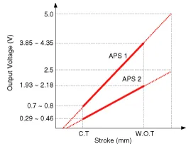
Description Accelerator Position Sensor (APS) is installed on the accelerator pedal module and detects the rotation angle of the accelerator pedal.
Circuit Diagram
Other information:
Kia Cadenza YG 2016-2021 Service Manual: Components and Components Location
C
Kia Cadenza YG 2016-2021 Service Manual: Antenna Coil Repair procedures
Removal 1. Disconnect the negative (-) battery terminal. 2. Remove the crash pad lower panel. (Refer to Body - "Crash Pad") 3. Disconnect the 6P connector (B) of the coil antenna and then remove the coil antenna (A) after loosening the screw.
Categories
- Manuals Home
- Kia Cadenza Owners Manual
- Kia Cadenza Service Manual
- Emission Control System
- Engine Control / Fuel System
- Components and Components Location
- New on site
- Most important about car

Copyright © 2026 www.kcadenzavg.com - 0.0236